Output Module Reference Data
E1 Output Module
176 SSU-2000 User’s Guide 12713020-002-2 Revision D – April 2004
Status LED Indicators
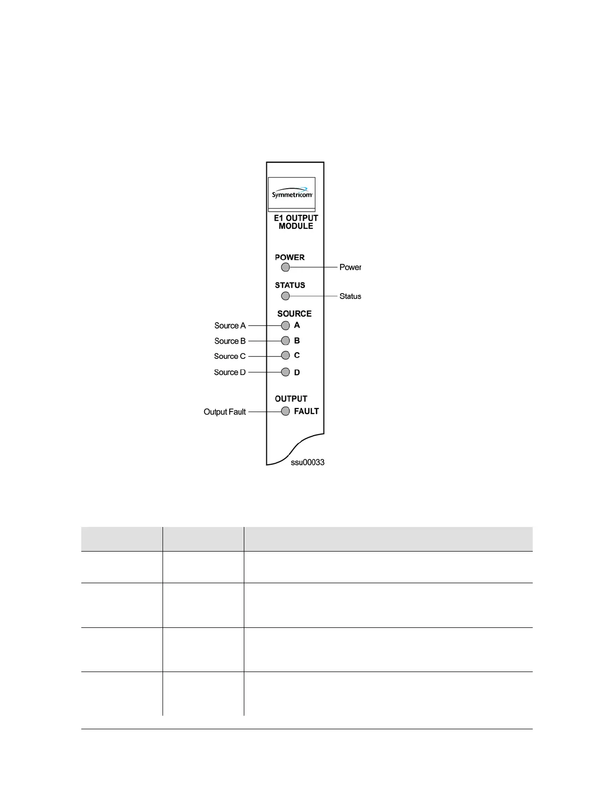
The E1 Output module has seven status LED indicators on the front panel of the
module that are used for visually conveying status information to the user. The
LEDs are shown in Figure 8-2 and described in Table 8-1.
Figure 8-2. Front Panel of the E1 Output Module
Table 8-1. E1 Output Module Status LED Indicators
Indicator Color Description
POWER Green On = +5 vDC power available on the Output module
Off = +5 vDC not present on the module
STATUS Green/Amber On (Green) = Module functioning correctly
Blinking Amber = Output module is downloading firmware
On (Amber) = Output module failure
SOURCE A Green/Amber On (Green) = Clock A in slot 1 is the selected source clock
On (Amber) = Faulty or missing Clock A
Off = Clock A is good and not selected
SOURCE B Green/Amber On (Green) = Clock B in slot 13 is the selected source clock
On (Amber) = Faulty or missing Clock B
Off = Clock B is good and not selected

 Loading...