12713020-002-2 Revision D – April 2004 SSU-2000 User’s Guide 161
Input Module Reference Data
1-Port and 3-Port DS1 Input Modules
Configuration Options
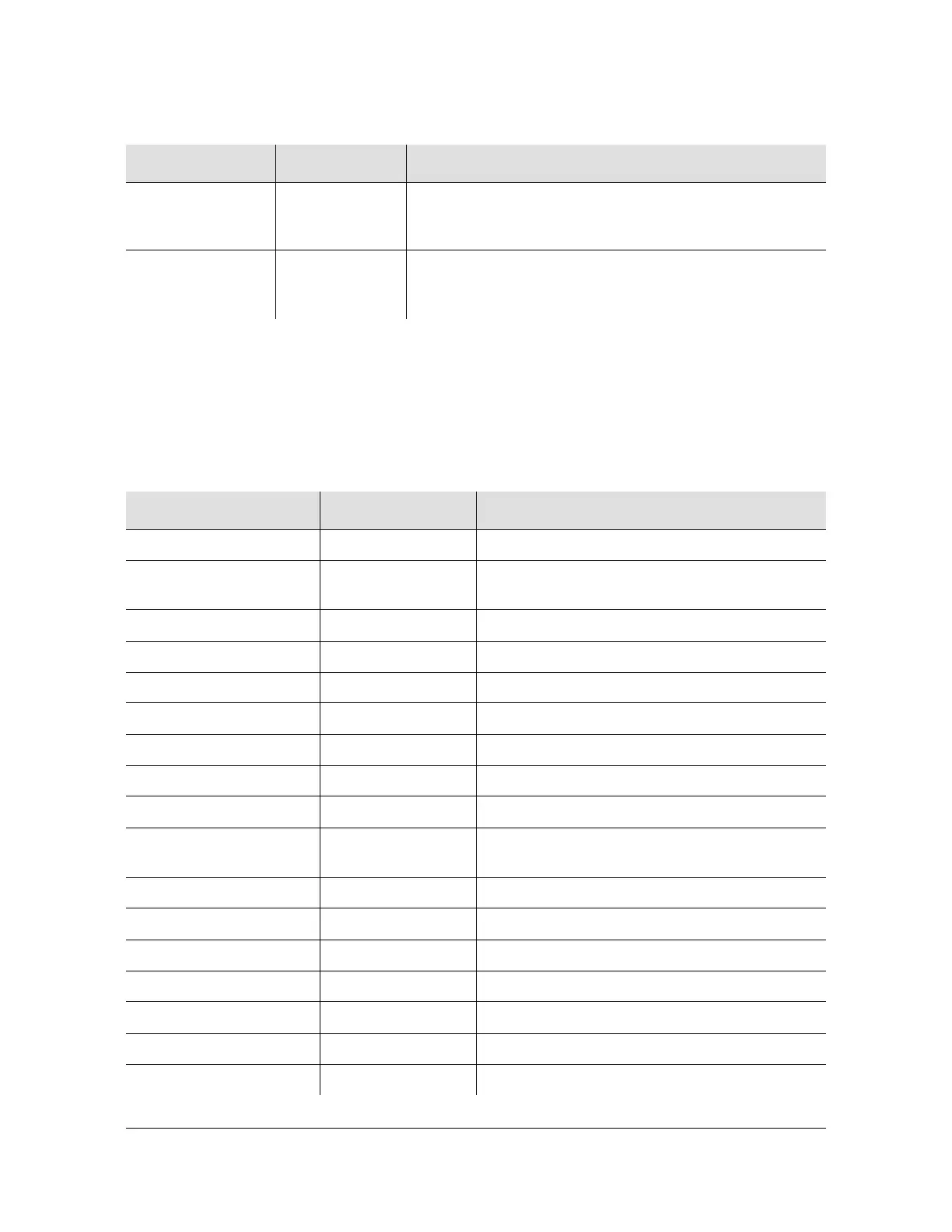
The factory settings and ranges for all DS1 Input module software parameters are
listed in Table 7-8.
PORT 3 REF Green/Amber On (Green) = Selected
On (Amber) = Not good and ignored
Off = Ignored or good and not selected
PORT 3 INPUT Green/Amber On (Green) = Selected
On (Amber) = Not good and ignored
Off = Ignored or good and not selected
Table 7-8. DS1 Input Module Configuration
Configuration Setting Factory Default Range
Framing Enabled On/On/Off On/Off
Input Frequency
(for unframed signals)
10 MHz 1 MHz, 1.544 MHz, 2.048 MHz, 5 MHz, 10MHz
Framing Type ESF D4 or ESF
Zero Suppression On On/Off
CRC Off On/Off
SSM Off On/Off
Provisioned PQL 3/4/3 1 to 16
Priority 0 0 to 10 (0 = Monitor)
Cesium Fault Nominal Low Low/High/Off
Input Signal Error Limit 10 seconds 1 to 100 for LOS and AIS
1 to 10000 for BPV, CRC and OOF
MTIE T10 Limit1 325/1000/325 0 to 100000
MTIE T10 Limit2 330/1010/330 0 to 100000
MTIE T100 Limit1 550/2000/550 0 to 100000
MTIE T100 Limit 2 560/2010/560 0 to 100000
MTIE T1000 Limit1 1010/2000/1010 0 to 100000
MTIE T1000 Limit2 1020/2010/1020 0 to 100000
MTIE T10000 Limit 1 1100/2835/1100 0 to 100000
Table 7-7. DS1 Input Module Status LED Indicators (Continued)
Indicator Color Description

 Loading...