12713020-002-2 Revision D – April 2004 SSU-2000 User’s Guide 413
Signal Names and Definitions
SDU-2000 Expansion Interface
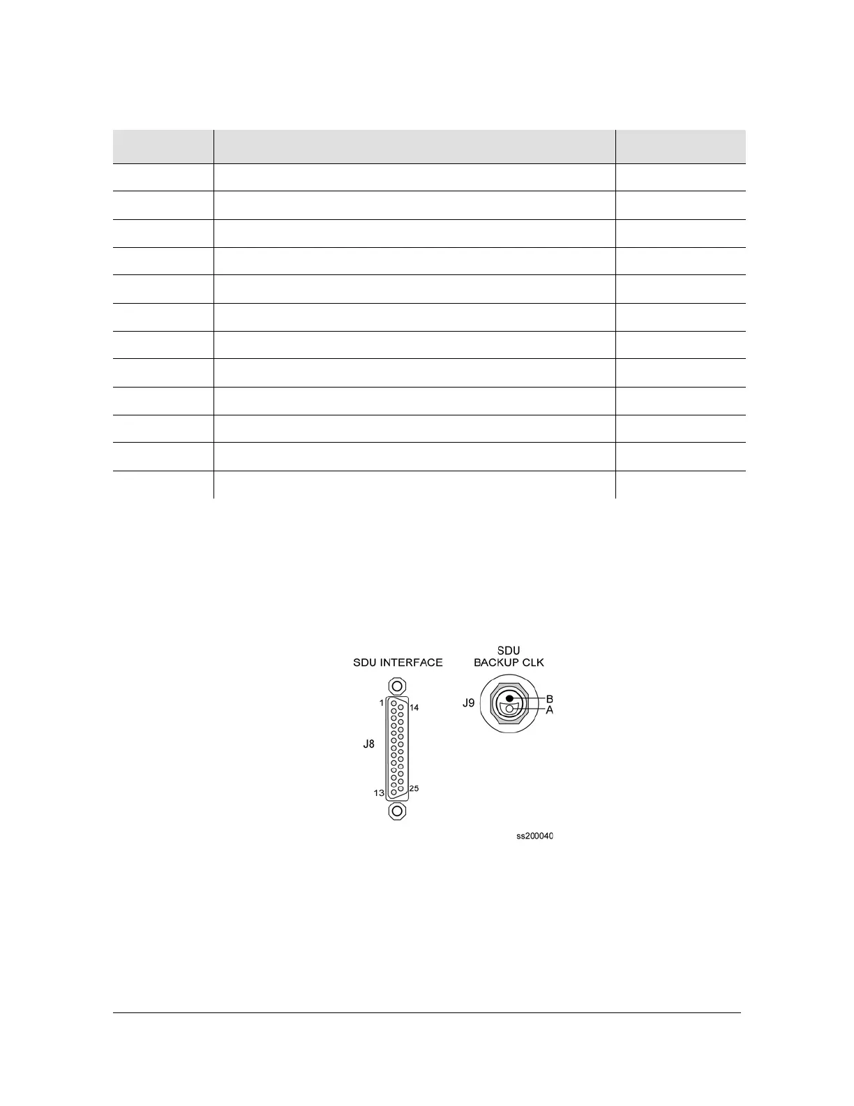
Figure D-6 illustrates the SDU Interface and the Backup Clock Connector, located
on the rear panel of the SSU-2000. Table D-5 outlines signal names, definitions,
and locations of the SDU Expansion interface and backup clock connectors.
Figure D-6. SDU Interface and Backup Clock Connector Pinouts
LMIN-NO Local Minor Alarm, Normally Open Contact TB1-7
LMIN-COM Local Minor Alarm, Common Contact TB1-8
LMIN-NC Local Minor Alarm, Normally Closed Contact TB1-9
RCRT-NO Remote Critical Alarm, Normally Open Contact TB2-1
RCRT-COM Remote Critical Alarm, Common Contact TB2-2
RCRT-NC Remote Critical Alarm, Normally Closed Contact TB2-3
RMAJ-NO Remote Major Alarm, Normally Open Contact TB2-4
RMAJ-COM Remote Major Alarm, Common Contact TB2-5
RMAJ-NC Remote Major Alarm, Normally Closed Contact TB2-6
RMIN-NO Remote Minor Alarm, Normally Open Contact TB2-7
RMIN-COM Remote Minor Alarm, Common Contact TB2-8
RMIN-NC Remote Minor Alarm, Normally Open Contact TB2-9
Table D-4. Signal Names and Locations of Alarms (Continued)
Name Description Connector–Pin

 Loading...