Signal Names and Definitions
410 SSU-2000 User’s Guide 12713020-002-2 Revision D – April 2004
Communication Interfaces
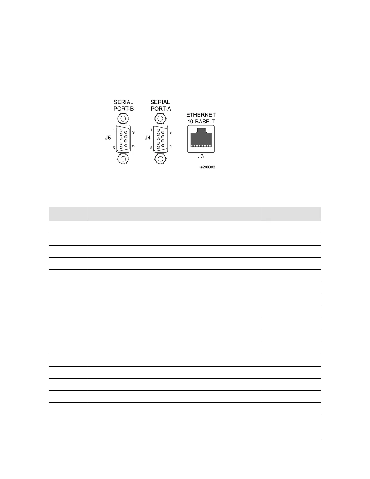
Figure D-3 shows the communications interfaces on the rear panel of the
SSU-2000. Table D-2 describes the signal names, definitions, and pinouts of
Communications connectors.
Figure D-3. Communications Interface Pinout
Table D-2. Pinouts of Communications Interfaces
Name Description Connector–Pin
DCD-A Serial Port A, Data Carrier Detect Control Line J4-1
DSR-A Serial Port A, Data Set Ready Control Line J4-6
RXD-A Serial Port A, Received Data J4-2
RTS-A Serial Port A, Request to Send Control Line J4-7
TXD-A Serial Port A, Transmitted Data J4-3
CTS-A Serial Port A, Clear to Send Control Line J4-8
DTR-A Serial Port A, Data Terminal Ready Control Line J4-4
RI-A Serial Port A, Ring Indicator Control Line J4-9
RTN-A Serial Port A, Signal Return J4-5
DCD-B Serial Port B, Data Carrier Detect Control Line J5-1
DSR-B Serial Port B, Data Set Ready Control Line J5-6
RXD-B Serial Port B, Received Data J5-2
RTS-B Serial Port B, Request to Send Control Line J5-7
TXD-B Serial Port B, Transmitted Data J5-3
CTS-B Serial Port B, Clear to Send Control Line J5-8
DTR-B Serial Port B, Data Terminal Ready Control Line J5-4
RI-B Serial Port B, Ring Indicator Control Line J5-9

 Loading...