Output Module Reference Data
Line Retiming Unit (LRU)
212 SSU-2000 User’s Guide 12713020-002-2 Revision D – April 2004
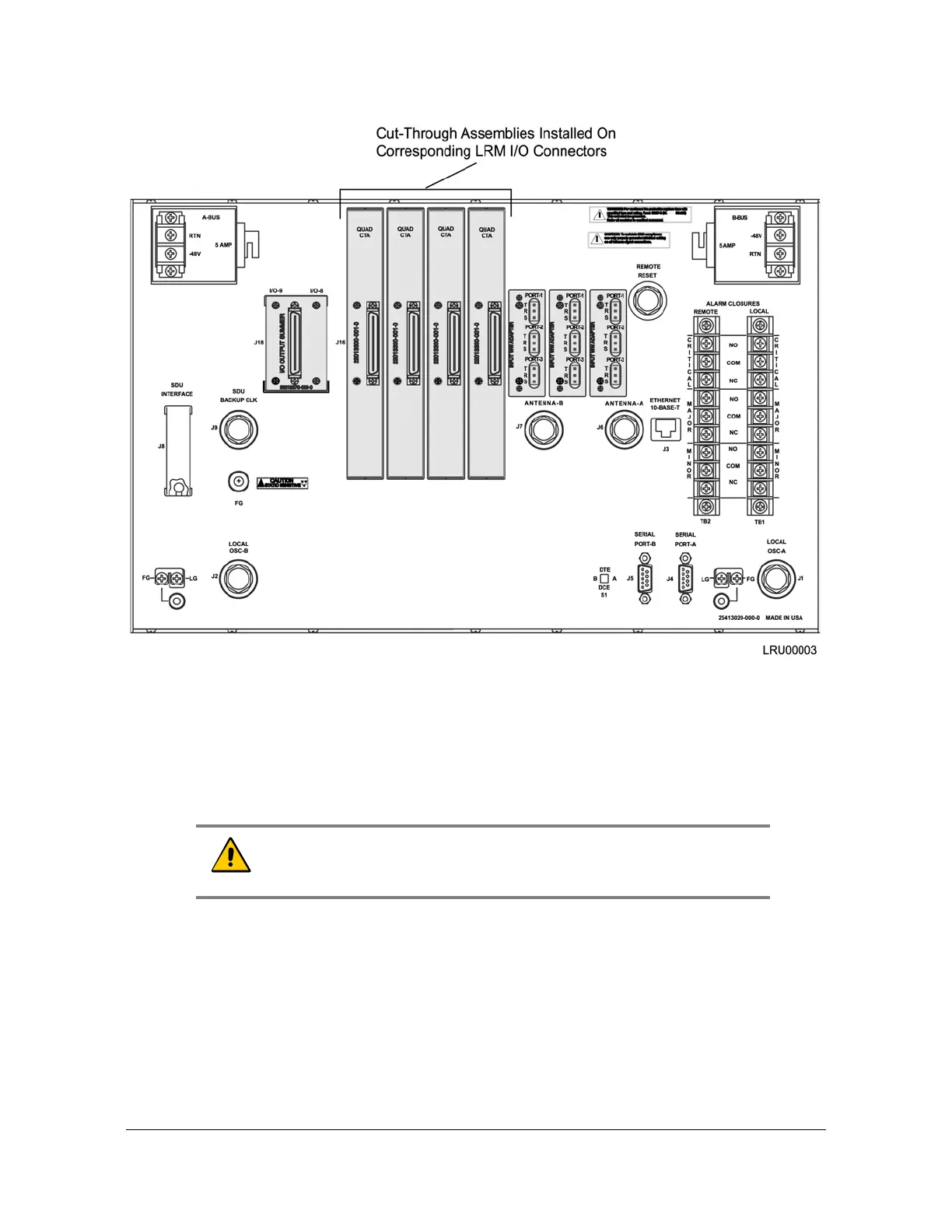
Figure 8-21. Installing the Cut-Through Assembly in the SSU-2000
Use the following steps to install the Cut-Through Assembly on an SSU-2000. Refer
to Table 8-17 for a description of the SSU-2000 and CTA I/O connector pin functions
and to Figure 8-23 for pin orientation.
1. Remove the two screws on each I/O connector that a CTA is to be installed on.
2. Install CTA connectors on all outputs corresponding to installed LRMs.
3. Tighten all CTA connector screws securely.
4. Connect 50-pin Micro-D output cables as required for your application.
Caution: To avoid possible electro-static discharge problems after
removing a CTA connector, you must replace the screws securing the
I/O connectors on the rear panel of the SSU-2000.

 Loading...