Input Module Reference Data
Input Adapter Panels
168 SSU-2000 User’s Guide 12713020-002-2 Revision D – April 2004
Factory Default (Basic) Configuration
The configuration settings for the Composite Clock Input module are listed in Table
7-12.
Input Adapter Panels
This section describes the input adapters available to connect typical
telecommunications signals to the rear panel of the SSU-2000 and SDU-2000.
Input Adapter Panel for 1-Port Input Module
Symmetricom offers three Input Adapter panels for use with 1-port Input modules.
Each panel has the following common features:
Accommodates up to four separate input signals
Switch-selected inputs allow for DE9 and another connector type
Switchable input termination impedance
Switch-selected link between signal and frame ground (when a frame ground is
connected to the lug on the rear panel)
1-m SCSI connection cable is included with the Adapter
The Input Adapter (part number 22013069-001-0) used with a 1-Port Input module
is shown in Figure 7-9. Each port has a switch-selected BNC and a DE9 connector,
and the input termination impedance is switch-selectable between 50, 75, 100, 120,
or 2.2 kΩ.
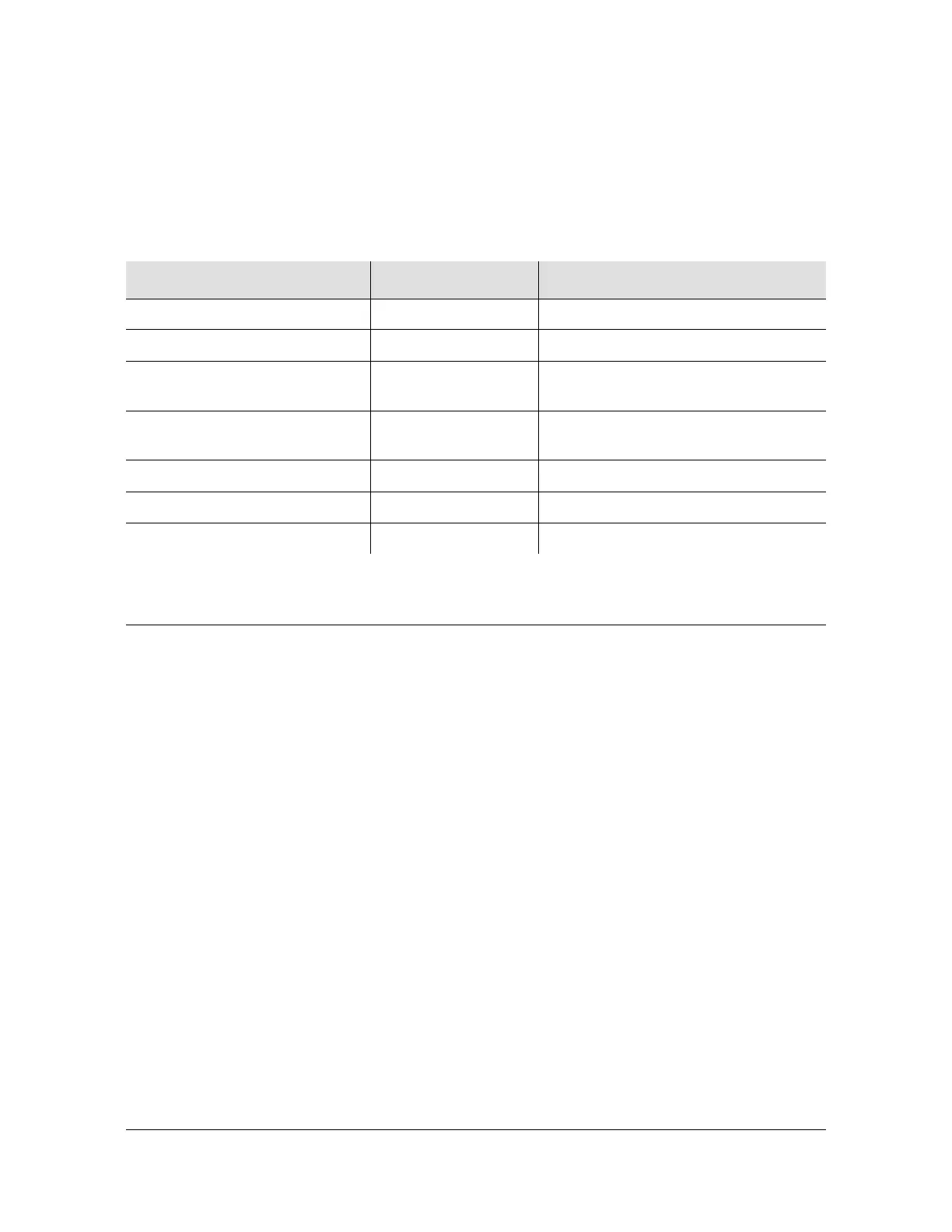
Table 7-12. Composite Clock Input Module Configuration Settings
Configuration Setting Factory Default Range
Provisioned PQL 4 1 – 16
Priority 0 1 – 10 (0 = Monitor)
Input Signal Error Limit LOS = 1, BPV = 1 LOS: 1 – 100
BPV: 1 – 100000
Input Signal Clear Limit LOS = 5, BPV = 5 LOS: 1 – 100
BPV: 1 – 100000
Alarm Elevation Time 86400 seconds 0 – 500000 seconds
Port Status Enabled Enabled/Disabled
Port Name None (blank) Any string from 0 – 20 characters

 Loading...