12713020-002-2 Revision D – April 2004 SSU-2000 User’s Guide 411
Signal Names and Definitions
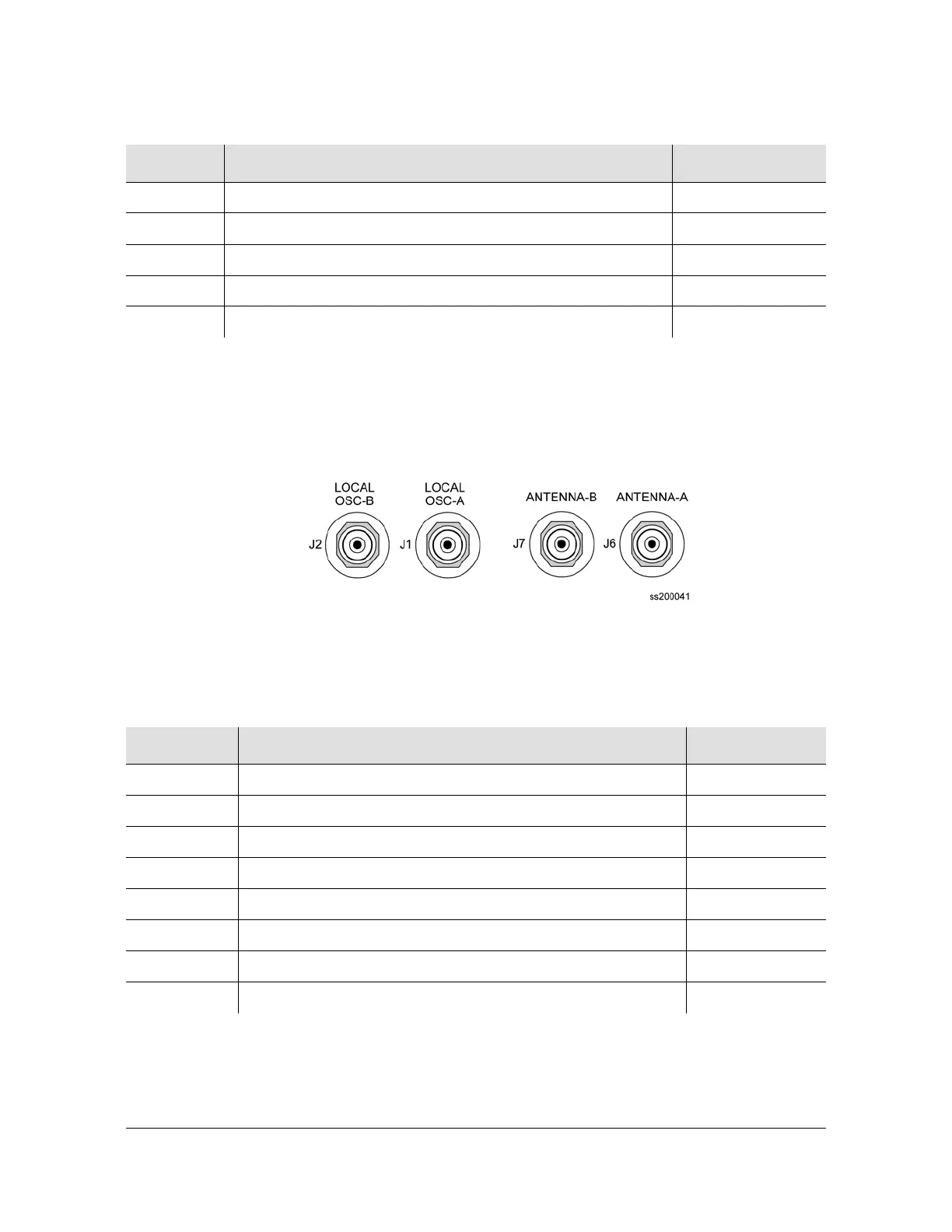
Local OSC and Antennas
Figure D-4 illustrates the location of the oscillator and antenna connectors. Table
D-3 describes the pinouts of local Oscillators and antenna connectors.
Figure D-4. Local Oscillator and Antenna Connectors
RTN-B Serial Port B, Signal Return J5-5
TX+ Ethernet 10-Base-T, Positive Side of Transmitted Data J3-1
TX- Ethernet 10-Base-T, Negative Side of Transmitted Data J3-2
RX+ Ethernet 10-Base-T, Positive Side of Received Data J3-3
RX- Ethernet 10-Base-T, Negative Side of Received Data J3-6
Table D-3. Signal Names and Locations of Local OSC and Antennas
Name Description Connector–Pin
LO-A+ Local Oscillator A, Positive Side of Signal J1-A (Ctr)
LO-A- Local Oscillator A, Negative Side of Signal J1-B (Shld)
LO-B+ Local Oscillator B, Positive Side of Signal J2-A (Ctr)
LO-B- Local Oscillator B, Negative Side of Signal J2-B (Shld)
ANT-A Antenna A, Center Conductor (Received Signal & Ant. Power) J6-A (Ctr)
ANT-A-RTN Antenna A, Return J6-B (Shld)
ANT-B Antenna B, Center Conductor (Received Signal & Ant. Power) J7-A (Ctr)
ANT-B-RTN Antenna A, Return J7-B (Shld)
Table D-2. Pinouts of Communications Interfaces (Continued)
Name Description Connector–Pin

 Loading...