Installing the SSU-2000
Making Connections
68 SSU-2000 User’s Guide 12713020-002-2 Revision D – April 2004
Installing Output Summer Adapters
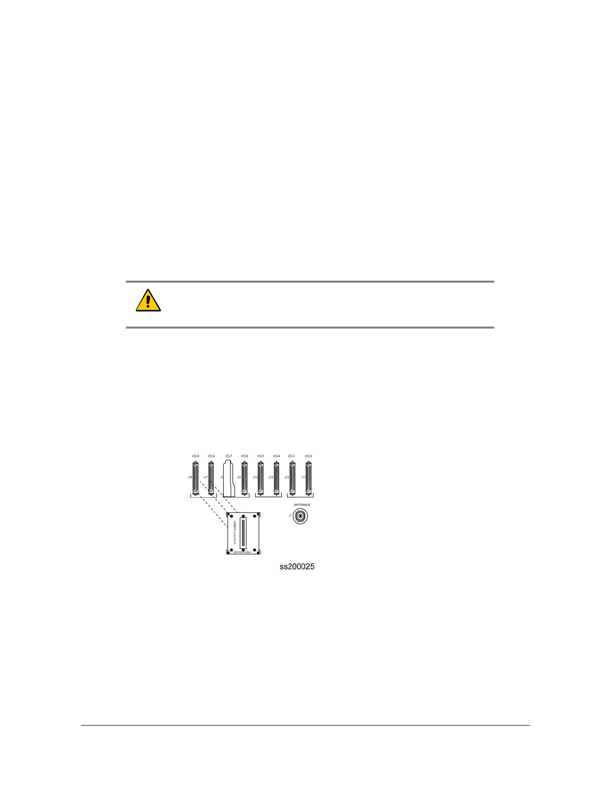
To create
an A/B pair of Output modules in a redundancy configuration, you need to
install Output Summer adapters (part number 22013070-000-0) on the
corresponding outputs as shown in
Figure 2-5
. All Module A outputs are summed
with the corresponding outputs of Module B, providing 1:1 output protection (1:1
redundancy). Output pairs in slots A4/A5, A6/A7, A8/A9, and A10/A11 are available
for configuration in redundant mode using Output Summer connectors. The pinout of
the Output Summer adapter is the same as the I/O interface connectors (see
Table
D-7
)
.
To install the Output Summer adapter:
1. Remove the two retaining screws on each connector that the Output Summer
adapter is to be installed on.
2. Install Output Summer adapters on all I/O connector pairs that require
redundancy, see Figure 2-5.
3. Tighten all Output Summer adapters screws securely.
4. Connect 50-pin Micro-D output cables between the I/O Adapter panel and the
Output Summer adapter as required.
Figure 2-5. Installing the Output Summer Adapter
Caution: To avoid possible electrostatic discharge problems after
removing an Output Summer adapter, you must replace the screws
securing the I/O connectors on the rear panel of the SSU-2000.

 Loading...