Provisioning and Operating the SSU-2000
Controls and Indicators
88 SSU-2000 User’s Guide 12713020-002-2 Revision D – April 2004
Controls and Indicators
SSU-2000 Status LED Indicators
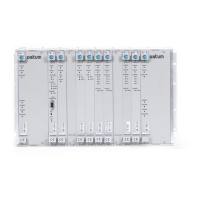
All modules used in the SSU-2000 main chassis and in the optional SDU-2000
Expansion shelf contain status LED indicators that provide a visual indication of
module status. The Communications module provides both system and individual
module status whereas all other modules provide individual module status only. For
more information on individual module status LED indicators, refer to Chapter 6,
Clock Module Reference Data, Chapter 7, Input Module Reference Data, and
Chapter 8, Output Module Reference Data.
SSU-2000 Operating Controls
The SSU-2000 contains four hardware operating controls:
Three DCE/DTE select switches associated with the three RS-232 ports. One
switch is located on the front of the Communications module and the remaining
two are located on the rear panel of the SSU-2000. The DCE position is for
connection to a PC and the DTE position is for connection to a modem.
Reset (RST) switch on the Communications module
All other controls on the SSU-2000 are software-based. To provision the settings,
you must first connect to the SSU-2000 using a serial port or the Ethernet port.
Establishing a Connection With the SSU-2000
You can connect to the SSU-2000 using either a serial connection or an Ethernet
connection. To connect via a serial port, see Communicating by Serial Port, on page
88. If the SSU-2000 is connected to an Ethernet LAN, use the procedure described
in Connecting through the Ethernet LAN.
Communicating by Serial Port
Three EIA-232 ports are available on the SSU-2000. Attach either a dumb terminal
or a PC with terminal emulation software to one of the ports as shown in Figure 3-1
(this example shows connecting to the local port on the front of the Communications
module).
1. Connect one end of the cable to the serial port on the computer or terminal and
the other to the appropriate connector on the SSU-2000.
2. Set the DTE/DCE switch on the rear panel of the SSU-2000 for the type of cable
(straight-through or modem).

 Loading...