12713020-002-2 Revision D – April 2004 SSU-2000 User’s Guide 191
Output Module Reference Data
E1/2048 kHz Output Module
E1/2048 kHz Output Signal Specifications
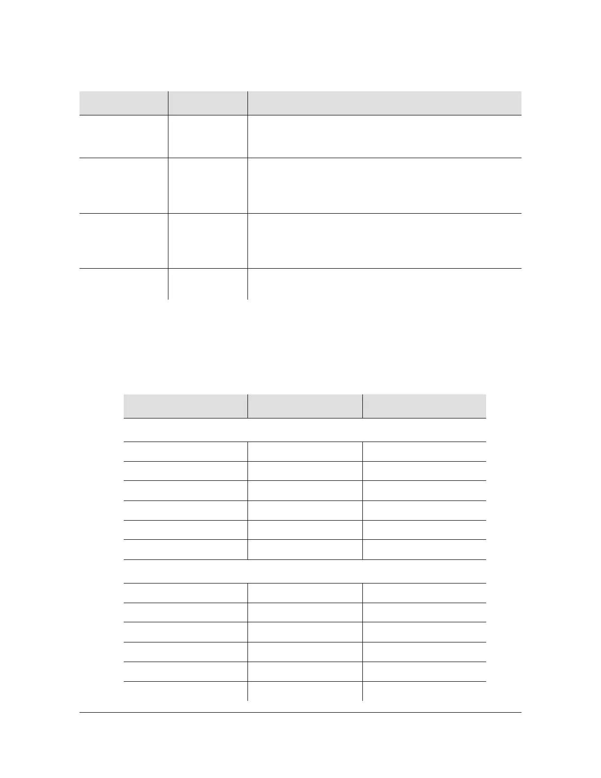
Specifications for the E1/2048 kHz Output signals are provided in Table 8-9.
SOURCE B Green/Amber On (Green) = Clock B in slot 13 is the selected source clock
On (Amber) = Faulty or missing Clock B
Off = Clock B is good and not selected
SOURCE C Green/Amber On (Green) = The Bypass clock (Clock C) is the selected
source clock. See Bypass Clock (Clock C), on page 32
On (Amber) = Faulty or missing Bypass clock
Off = Bypass clock is ignored, or good and not selected
SOURCE D Green/Amber On (Green) = The Expansion clock (Clock D) is the selected
source clock. The module is in an Expansion shelf
On (Amber) = Faulty or missing Expansion clock
Off = Expansion clock is ignored, or good and not selected
OUTPUT FAULT Amber On = Module has detected one or more faulty outputs
Off = All output signals are good
Table 8-9. E1/2048 kHz Output Module Specifications
Signal 120 Ω 75 Ω
E1
Specification ITU-T G.703/9 (10/98) ITU-T G.703/9 (10/98)
Signal AMI or HDB3 AMI or HDB3
Format CAS and CRC4 on CAS and CRC4 on
Cable Twisted pair, 120 Ω Coaxial, 75 Ω
Maximum Peak Voltage 3.3 V 2.61 V
Minimum Peak Voltage 2.7 V 2.13 V
2048 kHz
Specification ITU-T G.703/9 (10/98) ITU-T G.703/9 (10/98)
Signal Clock Clock
Format None None
Cable Twisted pair, 120 Ω Coaxial, 75 Ω
Maximum Peak Voltage 1.90 V 1.50 V
Minimum Peak Voltage 1.00V 0.75 V
Table 8-8. E1/2048 kHz Output Module Status LED Indicators (Continued)
Indicator Color Description

 Loading...