12713020-002-2 Revision D – April 2004 SSU-2000 User’s Guide 41
Product Overview
System Components
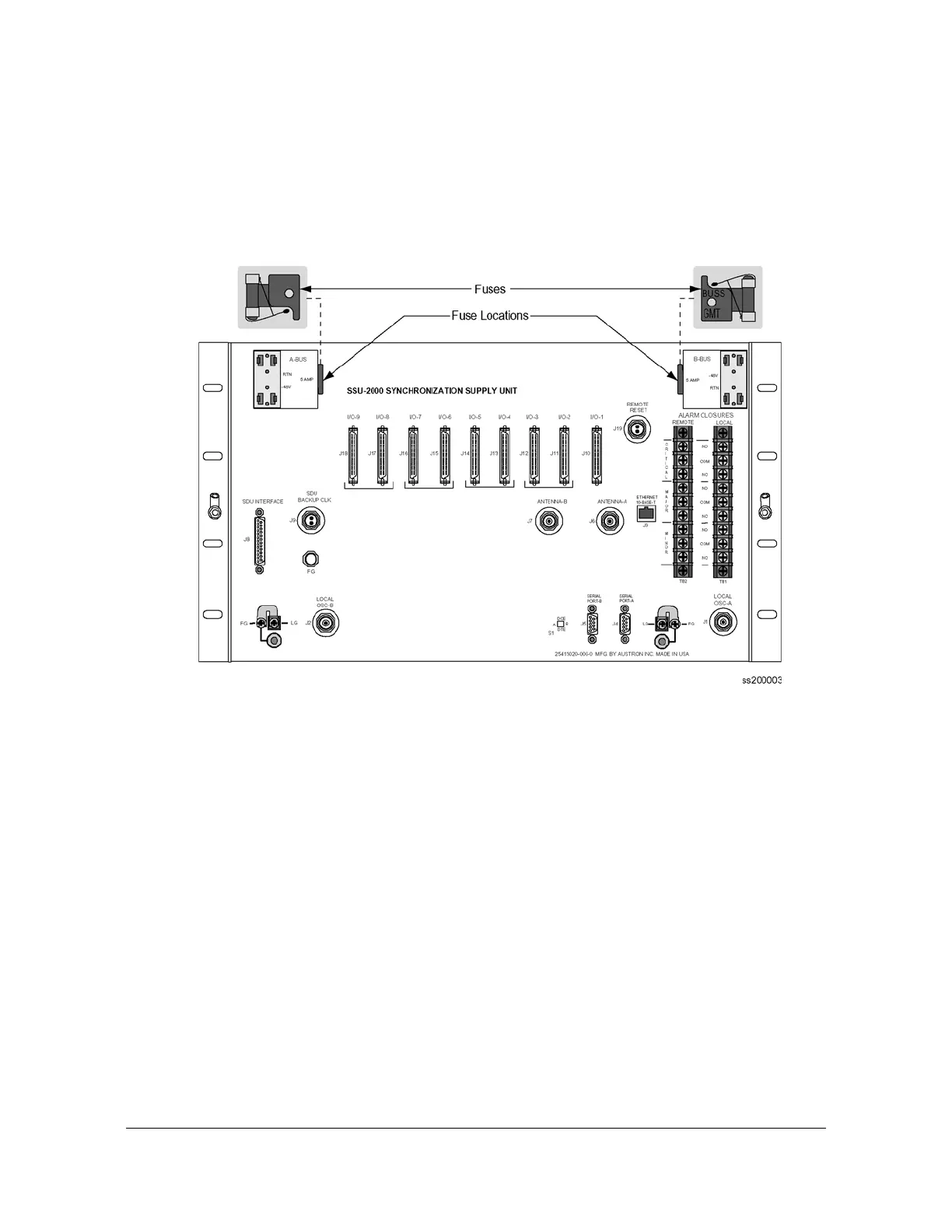
All power supplies for the SSU-2000 are implemented on the individual modules
which increases system availability by eliminating a single point of failure in the
power supply area. On each plug in module, diodes combine the two power sources
and provide protection from reversal of the power connections on the shelf (+ and –
reversed). Screw type lugs on the rear of the shelf are used for logic and shelf
ground connections.
Figure 1-9. Location of Power Fuses on the Rear Panel
Antenna Connectors
The SSU-2000 contains two TNC connectors to allow for connection of a radio
antenna. Connector J6 is wired into I/O slot A3 and connector J7 is wired into I/0
slot A5 (the only slots that can be used for installing a Radio input module). A variety
of GPS antennas are available as accessories for the SSU-2000, see Appendix C,
Antennas.
Communication Ports
The SSU-2000 main shelf contains four communication ports, including:
Two RS-232 communication ports (Port A and Port B) on the rear panel of the
main shelf
One RS-232 port on the face of the Communications module (Port C)
One RJ-45 Ethernet connector on the rear panel of the SSU-2000 (Ethernet
10-Base-T) for network connection

 Loading...