12713020-002-2 Revision D – April 2004 SSU-2000 User’s Guide 233
Hardware Configuration Guide
SSU-2000 Configuration Chart
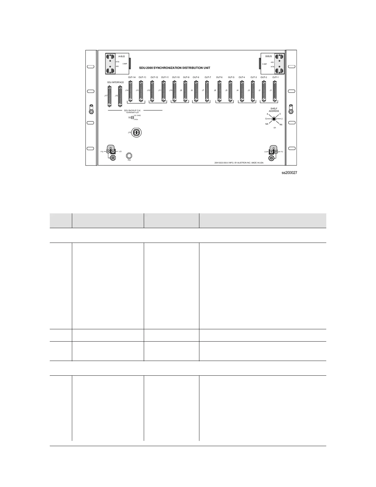
Figure 9-5. SDU-2000 Synchronization Distribution Unit
Table 9-3. SSU-2000 System Components
Item Description Part Number Notes
SSU-2000 Main Shelf and Associated Hardware
1. SSU-2000 Main Shelf
(Chassis) with SDU
termination plug and
SSU-2000 User’s
Guide
(12713030-002-2)
25413020-000-0 Required for all systems. Requires minimum
of one Comms module, one Clock module,
one Input module, one Output module, one
Input Adapter panel and one Output adapter
panel and 8 Filler panels (including one wide
panel).If an Expansion shelf (SDU-2000) is
not installed, SSU Expansion Terminator,
part number 12013049-000-0 must be
installed on J8 on the SSU-2000 chassis.
Otherwise, the terminator must be installed
on the last Expansion shelf in the system.
2. Bracket, rack ear, 19” 00413102-000-1 Two each provided with the main shelf.
3. Bracket, rack ear, 23”,
2 each required
00413020-001-1 Two each required per main shelf
(must specify 23” rack).
Clock Modules
4. Stratum 2E Rb Clock
Module
23413016-000-0 Minimum of one Clock module per system
(item 4, 5, or 6).
Redundant configuration with automatic
switching in case of clock failure requires
two Clock modules.
The system will operate with 2E/3E clocks
combined. 2E clock must be installed in
chassis slot A1.

 Loading...