12713020-002-2 Revision D – April 2004 SSU-2000 User’s Guide 67
Installing the SSU-2000
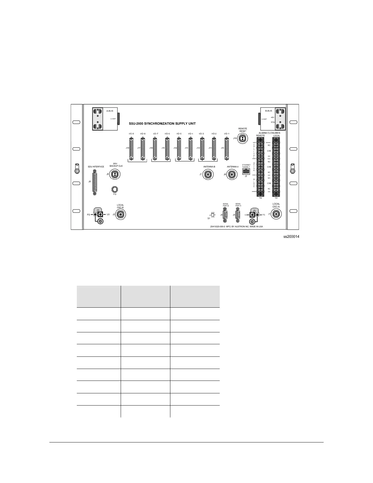
Making Connections
All I/O connections are made through the nine 50-Pin Micro-D female connectors,
J10 through J18. Each connector is associated with a specific chassis slot. Table
2-1 lists the relationship between the I/O slot and the rear panel connector.
Connectors J10 through J18 are labeled I/O-1 through I/O-9. The signal
connections on these I/O connectors are set up in differential pairs as Tip and Ring
connections.
Figure 2-4. SSU-2000 Rear Panel
Table 2-1. I/O Module Slot to I/O Connector Relationship
Label
(Name)
Chassis Slot I/O Connector
I/O-1 A3 J10
I/O-2 A4 J11
I/O-3 A5 J12
I/O-4 A6 J13
I/O-5 A7 J14
I/O-6 A8 J15
I/O-7 A9 J16
I/O-8 A10 J17
I/O-9 A11 J18

 Loading...