Input Module Reference Data
GPS Input Module
164 SSU-2000 User’s Guide 12713020-002-2 Revision D – April 2004
Status LED Indicators
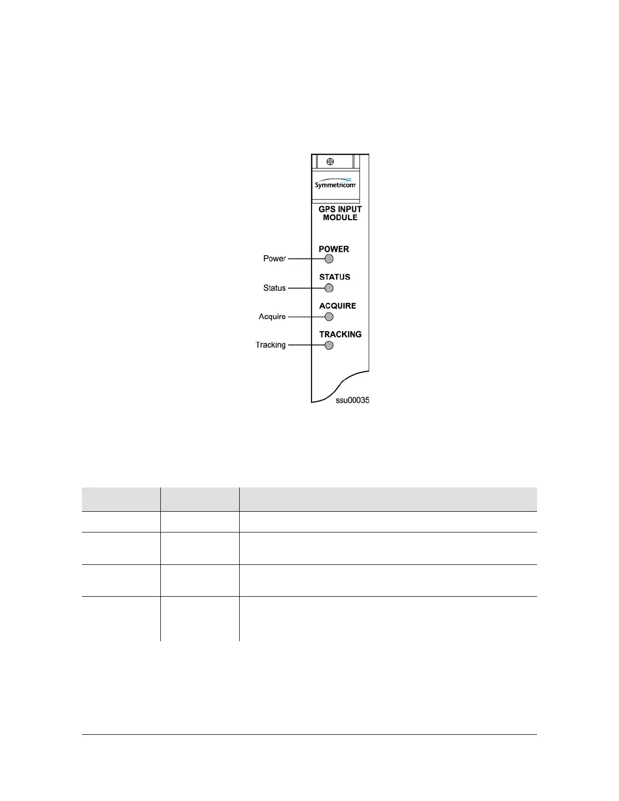
The GPS Input module is equipped with four status LEDs as shown in Figure 7-6.
The LED status assignments are described in Table 7-9.
Figure 7-6. Front Panel of the GPS Input Module
Table 7-9. GPS Input Module Status LED Indicators
Indicator Color Description
POWER Green On = The module is receiving +5 vDC
STATUS Green/Amber Green = Unit is in Normal mode of operation; no faults
Amber = Fault condition detected (firmware timed out)
ACQUIRE Green/Amber On (Green) = Selected as the clock reference
Off = Not selected as clock reference
TRACKING Green/Amber On (Green) = Radio is tracking
On (Amber) = Tracking problem without antenna fault
Blinking (Amber) = Antenna fault

 Loading...