Product Overview
System Components
36 SSU-2000 User’s Guide 12713020-002-2 Revision D – April 2004
The unit is capable of generating reports to include: local oscillator being switched,
log in/out, restart, board removed/inserted, events cleared, PLL loop control, user
image clear/set, phase samples, frequency control, and a keep alive output every 5
minutes. See Appendix B, Communications Protocol, for information on commands.
Alarms and all events are reported over the communication ports and contain
details of the event in a single message including the time of the event. All ALARM
indications clear when the conditions that caused them no longer exist. In addition,
normal operating status is indicated by green LEDs on the front panel of modules.
Fail Mode
In the FAIL mode, the SSU-2000 removes the failed module from service or
usability to prevent interruption of the system. For example, a FAIL event detected
in Clock A causes a switchover from Clock A to Clock B, effectively removing Clock
A from the system. The FAIL event is reported on all communications ports and an
alarm is generated.
System Components
A fully expanded SSU-2000 installation contains the following physical components:
SSU-2000 Main shelf populated with various combinations of Clock, Input,
Output and Communications modules
Input and Output Adapter panels
Up to four SDU-2000 Expansion shelves containing Buffer and Output modules
SSU-2000 Main Shelf (Chassis)
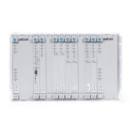
The SSU-2000 main shelf (shown in Figure 1-6) contains a metal chassis and a
motherboard with provisions for supporting up to 12 hot-swappable modules. Filler
panels are available for use in shelves that are not fully populated.
Note: For additional information about each of the module types, see
Chapter 6, Clock Module Reference Data, Chapter 7, Input Module
Reference Data, and Chapter 8, Output Module Reference Data. See
Chapter 9, Hardware Configuration Guide, for component part
numbers and guidelines for configuring a new system.

 Loading...