Installing the SSU-2000
Making Connections
70 SSU-2000 User’s Guide 12713020-002-2 Revision D – April 2004
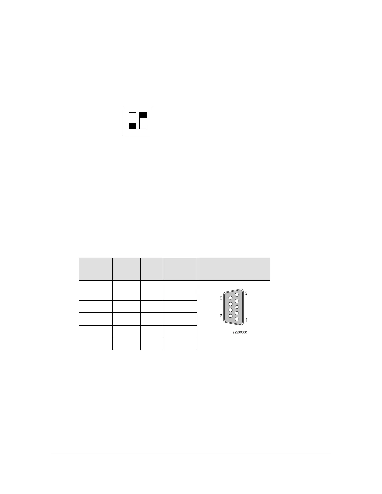
Serial Port DTE/DCE Switch
The serial port DTE/DCE switch is located on the lower right side of the rear panel,
as shown in Figure 2-6. Each port (A and B) may be configured as either DCE
(default, connection to PC) or DTE (connection to modem). The right switch controls
port A and the left switch controls port B.
Figure 2-6. DPDT Slide Switch
The default EIA-232 settings for both serial ports are 9600 baud, no parity, 8 data
bits, 1 stop bit, echo on, ASCII mode, and handshaking disabled. To change these
settings, connect the SSU-2000 to a terminal device or PC using a serial
communications program protocol. See Communicating by Serial Port, on page 88,
for more information.
Table 2-3 shows the EIA-232 Connector pin assignments for the SSU-2000 DE9
communications connectors.
Making Ethernet Connections
The Ethernet 10-Base-T connection is located on the rear panel connector J3,
which is a shielded RJ45 receptacle labeled Ethernet 10-Base-T. See
Communicating by Ethernet, on page 90, for more information on connecting and
using the Ethernet port.
Table 2-3. EIA-232 Connector Pin Assignments
Signal Pin Pin Signal
Connector
Orientation DE9S
FG Shield 5 Logic
Return
94DSR
CTS 8 3 TXD
RTS 7 2 RXD
DTR 6 1 DCD
DTE
DCE
S1
BA

 Loading...