12713020-002-2 Revision D – April 2004 SSU-2000 User’s Guide 183
Output Module Reference Data
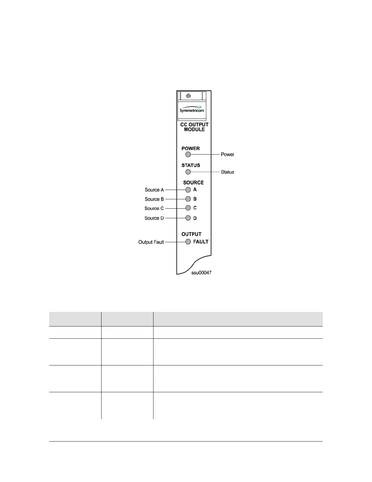
Composite Clock Output Module
Status LED Indicators
The Composite Clock Output module status LED indicators are shown in Figure 8-6
and described in Table 8-5.
Figure 8-6. Front Panel of the Composite Clock Output Module
Table 8-5. Composite Clock Output Module Status LED Indicators
Indicator Color Description
POWER Green On = +5 vDC power available on the Output module
STATUS Green/Amber On (Green) = Module functioning correctly
Blinking Amber = Output module is downloading firmware
On (Amber) = Output module failure
SOURCE A Green/Amber On (Green) = Clock A in slot 1 is the selected source clock
On (Amber) = Faulty or missing Clock A
Off = Clock A is good and not selected
SOURCE B Green/Amber On (Green) = Clock B in slot 13 is the selected source clock
On (Amber) = Faulty or missing Clock B
Off = Clock B is good and not selected

 Loading...