Bus setups Select the Bus clock channel polarity
Select the Bus clock channel polarity
From the Bus Setup window, select a bus, select the Parallel bus type, and click Clocked.
To use
Connect a probe between the instrument and the clock signal in your system under test.
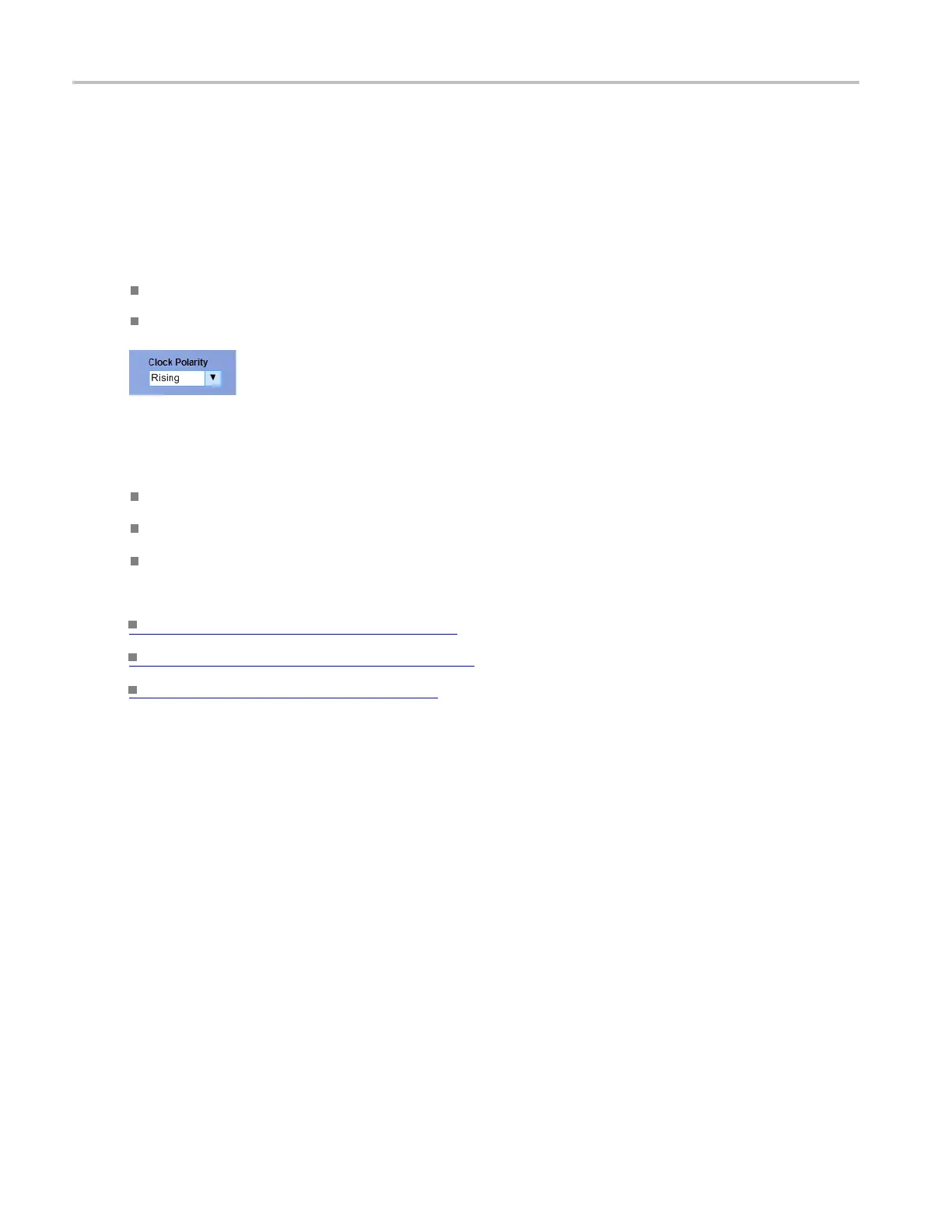
Click the Clock Polarity selection box and select from Rising, Falling, or Either.
Behavior
Rising causes the instrument to acquire data on the rising edge of the signal.
Falling causes the instrument to acquire data on the falling edge of the signal.
Either causes the instrument to acquire data on the rising and the falling edges of the signal.
What do you want to do next?
Learn more about b us setups. (see page 95)
Learn
about bus configuration.
(see page 148)
Learn about digital setups. (see page 87)
Bus setup control window (Display tab)
From the Bus Setup window, select the Display tab.
Ov
erview
Use the Bus Setup Display window to define how the instrument displays data acquired from the selected
b
us.
148 DSA/DPO70000D, MSO/DPO/DSA70000C, DPO7000C, and MSO/DPO5000 Series
 Loading...

