Mask testing setups Set up mask testing source/tolerance
Behavior
The Segment up and down arrows increase or decrease the segment number by one. The Vertex up and
down arrows increase or decrease the vertex by 1. To set a spe cific number, click in the Vertex entry
box to activate the pop-up calculator.
Clicking the Add button adds a p oint to the boundary in the selected segment and just after the selected
vertex in addition to moving any points that follow the newly added point in the boundary up one. For
example, if there are 6 points in the boundary of the selected segment and you add a point when the
selected vertex is 4, then the vertex w hich was 4 becomes vertex number 5, number 5 becomes 6, and
vertex 6 is changed to vertex 7.
Clicking Del deletes the se
lected vertex from the selected segment and moves any points that follow the
deleted point down one in the boundary. Clicking Del All deletes all points in the selected segment,
effectively deleting that segment.
Clicking the Setup button will return you to the Masks Testing control window. Clicking the Controls
button will activate the User Mask Edit control window
(see page 234) where you can make quick changes
to a User mask.
What do you want to do next?
Learn about saving masks. (see page 536)
Learn about recalling s aved masks. (see page 235)
Learn more about mask types. (see page 209)
Learnmoreaboutmasksetups. (see page 209)
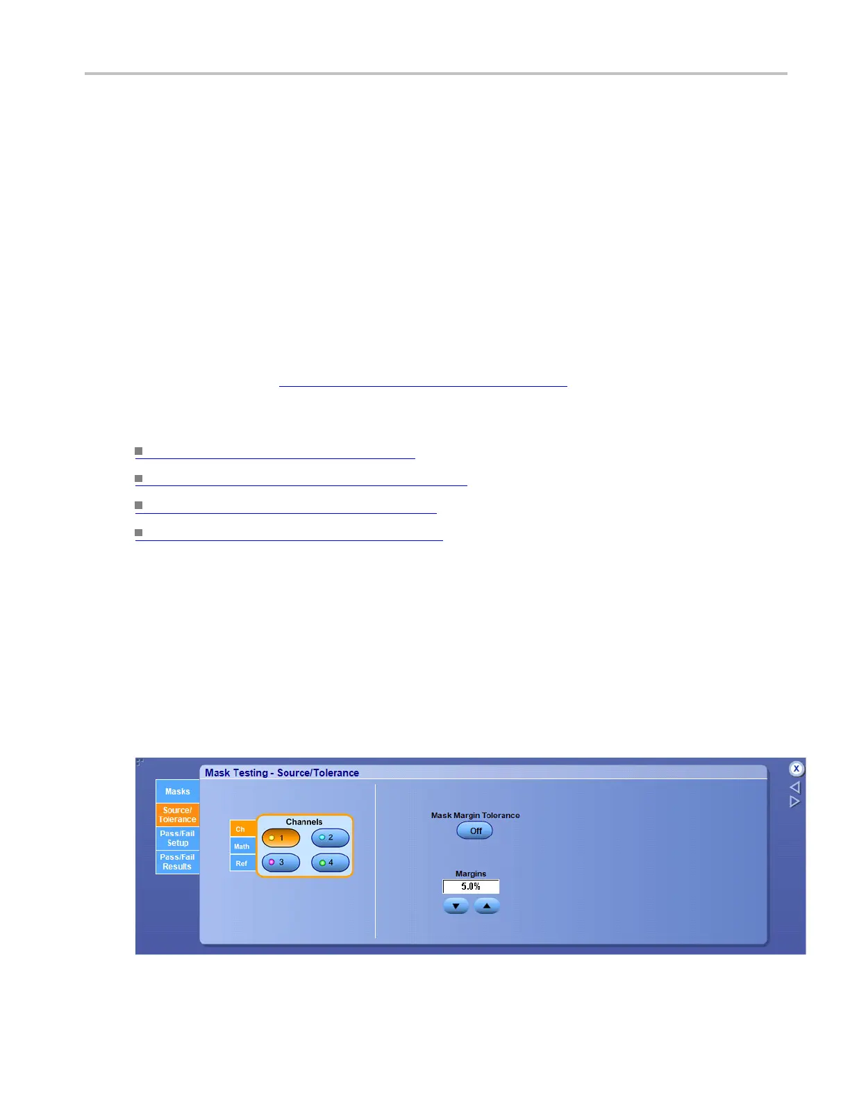
Set up mask testing source/tolerance
From the Mask menu, select Source.
Overview
Use this control window to select the source of the signal you want to test.
For information o n the controls, click the buttons.
DSA/DPO70000D, MSO/DPO/DSA70000C, DPO7000C, and MSO/DPO5000 Series 219
 Loading...

