Oscilloscope Reference Trigger coupling
Trigger coupling
Trigger c oupling determines what part of the signal is passed to the trigger circuit. Edge triggering can use
all available coupling types: AC, DC, Low Frequency Rejection, High Frequency Rejection, and Noise
Rejection. A
ll of the advanced trigger types use DC coupling only. For a description of each coupling
type, click here
(see page 62).
What do you w
ant to do next?
Learn about trigger position. (see page 701)
Learn about trigger holdoff. (see page 699)
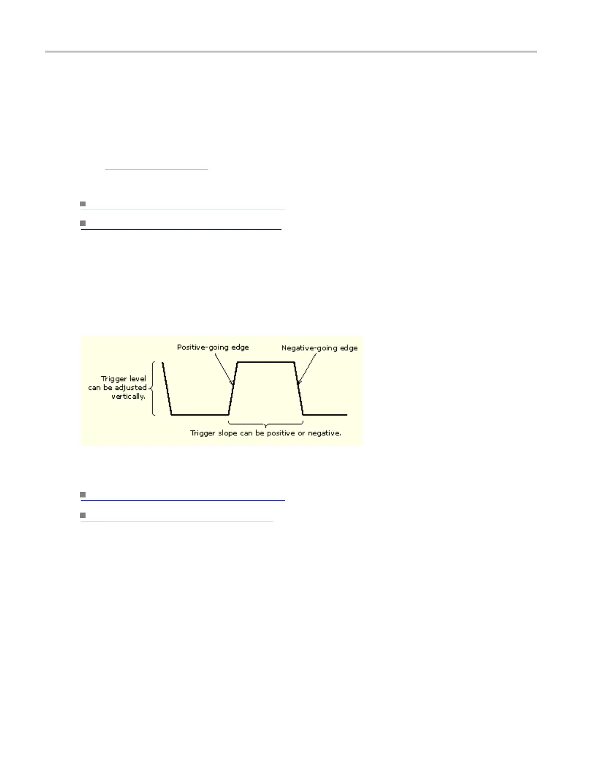
Trigger slope and level
The slope control determines whether the instrument finds the trigger point on the rising or the falling edge
of a signal. The level control determines where on that edge the trigger point occurs. See the next figure.
What do you want to do next?
Learn about trigger position. (see page 701)
Lea
rn about trigger slope.
(see page 700)
700 DSA/DPO70000D, MSO/DPO/DSA70000C, DPO7000C, and MSO/DPO5000 Series
 Loading...

