Controls and connectors Trigger controls
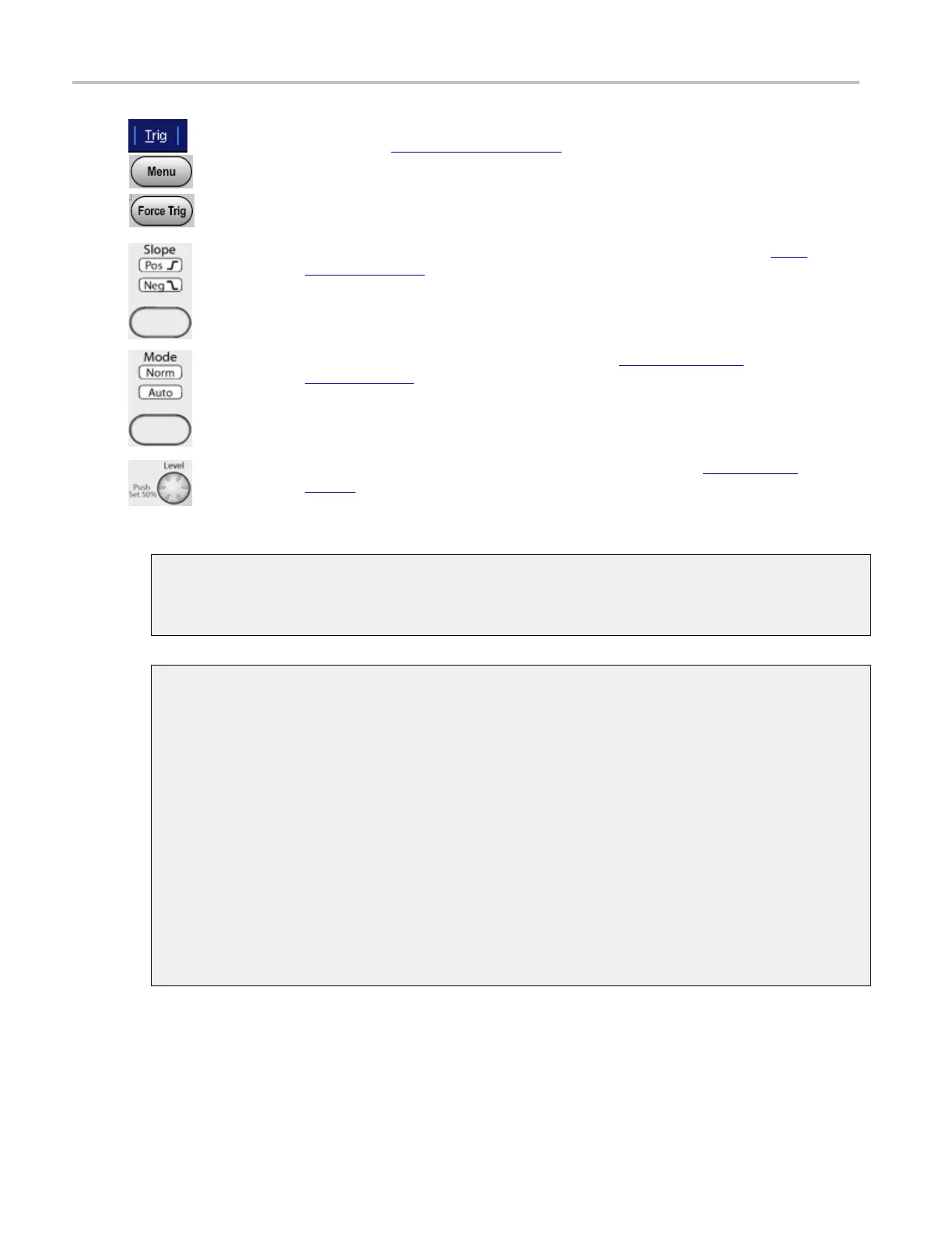
Select Trig in
the menu bar to open the Trigger control window. Use the Coupling drop-down
menu to select trigger coupling
(see page 62) for an A event or B event Edge trigger.
To open the Trigger control window, push the Menu button (Available only on MSO/DPO5000
Series instru
ments only).
Push the Force Trig button for the running trigger (Available only on MSO/DPO5000 Series
instruments only).
Push the button in the Slope column to toggle between positive, negative, or both trigger
slopes (see
page
63) for the Edge trigger. The selected trigger slope(s) are lighted. These
buttons are only valid for the A event Edge trigger.
NOTE. The trigger slope selection button is not available on MSO/DPO5000 Series
instrument
s.
Push the button in the Mode column to toggle between Normal (see page 63) (Norm) and
Auto
(see page 63) (Automatic) modes; the selected trigger mode is lighted.
NOTE. The trigger mode selection button is not available on MSO/DPO 5000 Series
instruments.
Push the Level knob to set the trigger level to 50%. To set a different trigger level (see
page 63), rotate the Level knob. The trigger level appears on the screen. The trigger level
knob aff
ects Edge, Width, Glitch, Timeout, Serial, Video and some Communications trigger
types.
xxx
Trigger source
The tri
gger source determines the source of the trigger signal. The input channels are the most
commonly used trigger sources and are available for all trigger types.
Trigger coupling
The t
rigger coupling determines w hat part of the signal is passed to the trigger circuitry. All trigger
types except edge triggering use DC coupling only. Edge triggering can use all available coupling
choices.
DC. This coupling passes all input signals to the trigger circuitry.
AC.
This coupling passes the input signals above 60 Hz to the trigger circuitry.
HF Reject. This coupling attenuates signals above 50 kHz before passing the signal to the trigger
ci
rcuitry.
LF Rej. This coupling attenuates signals below 80 kHz before passing the signal to the trigger
c
ircuitry.
Noise Rej. This coupling provides stable triggering by increasing the trigger hysteresis. Increased
hysteresis reduces the trigger sensitivity to noise but may require greater signal amplitude.
62 DSA/DPO70000D, MSO/DPO/DSA70000C, DPO7000C, and MSO/DPO5000 Series
 Loading...

