Vertical Setups Probe Setup Control Window: Probe Compensation
3. Click the D7-D0 or the D15-D8 tab, and then the desired digital channel buttons to activate the
controls for the logic source.
4. From the Vertical menu, select Probe Controls, and then click the Setup button.
5. Click the Properties button to display information on the logic probe and the status of the trigger
path alignment.
What do you want to do next?
Learn about setting u p the digital channels. (see page 88)
Learn about digital setups. (see page 87)
Learn abou
t setting up a bus.
(see page 95)
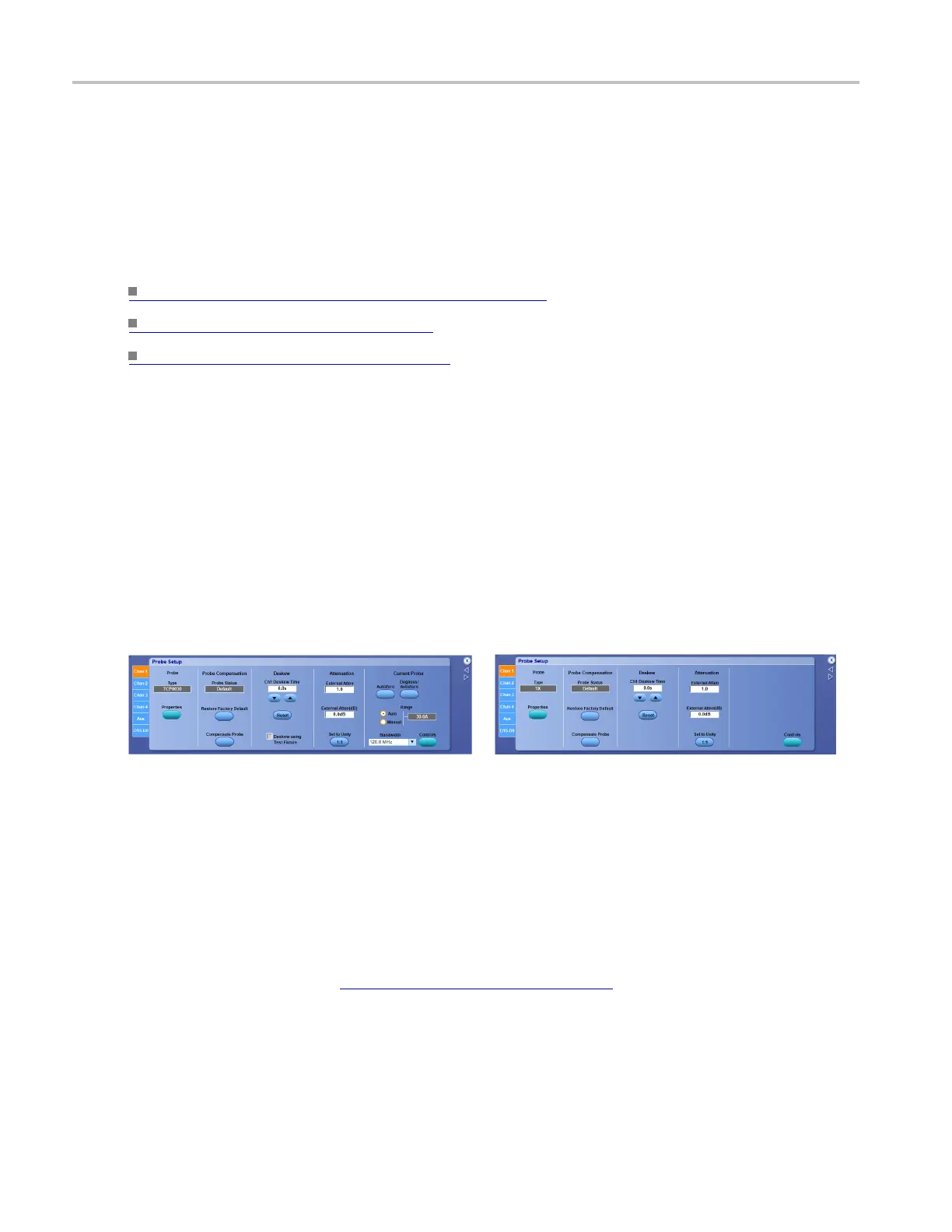
Probe Setup Control Window: Probe Compensation
From the Vertical menu, select Probe Cal.
Overview
Use the Probe Setup control window to compensate a probe; this will improve the gain and offset accuracy.
Probe compensation is specific to the channel to which it is connected.
Click for <4 GHz instruments: Click for ≥4 GHz instruments:
xxx
To use
1. Connect a probe to a vertical input.
2. Press a front panel Ch <1–4> button to activate the channel.
3. In the Probe Setup window, click a Chan <1–4> tab to activate the controls for the input s ource.
4. Select the probe Type for the appropriate signal and ground connections of the probe compensation
terminals.
For some probes, click the Probe Tip Select button
(see page 504) and select the tip that matches
the one you are using.
5. Click Restore Factory Default to clear the old values.
6. Click Compensate Probe to begin the procedure.
502 DSA/DPO70000D, MSO/DPO/DSA70000C, DPO7000C, and MSO/DPO5000 Series
 Loading...

