Error detector setups Specify the error d etector test pattern
Specify the error detector test pattern
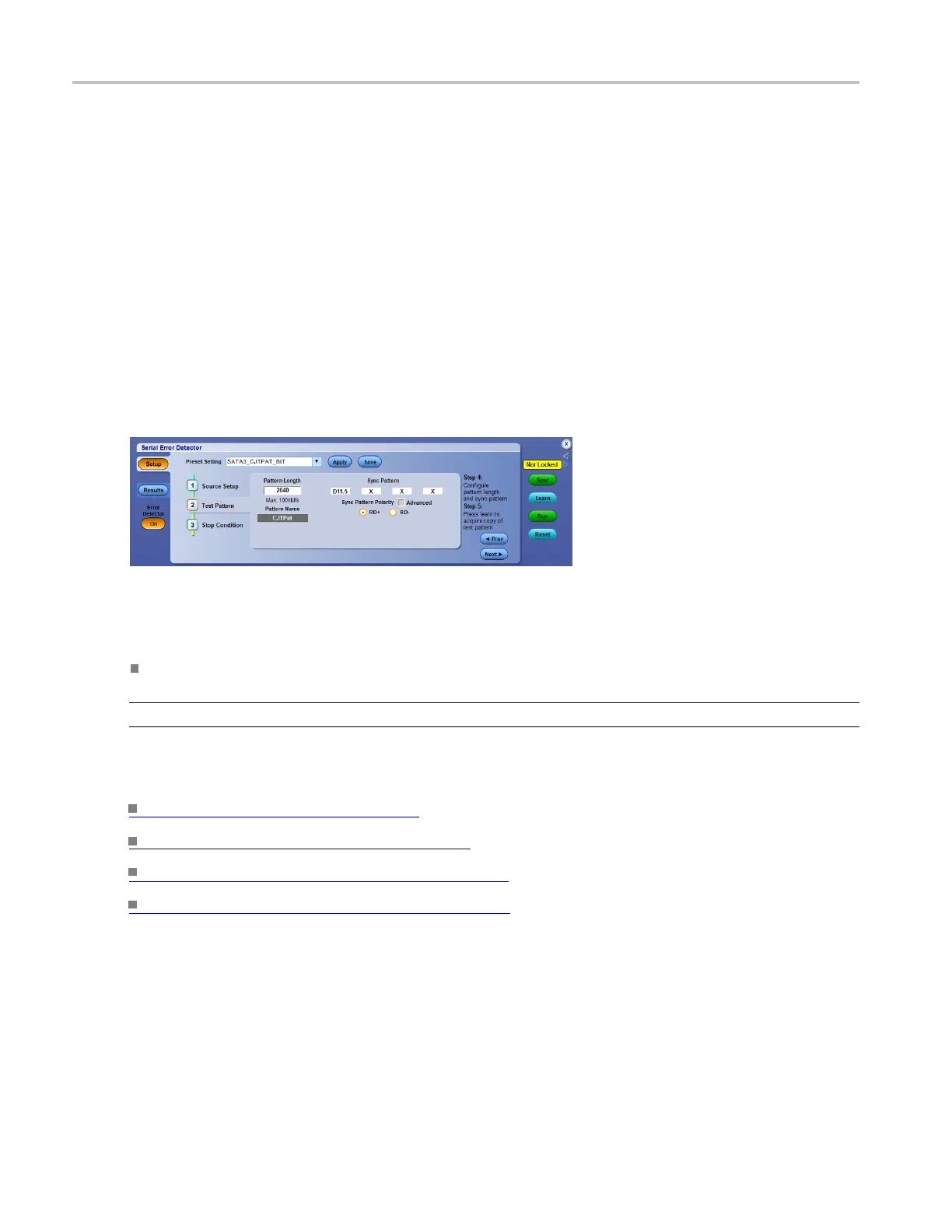
From the Analyze menu, select Serial Error Detector, press Setup, and then select the Test Pattern tab.
Overview
The Test Pattern Setup provides control of the signal test pattern length and the Sync Pattern description.
These are of
ten the most difficult settings, because they require knowledge of the signal. The Pattern
Length is the number of bits in the repeating signal being sent to the DUT or oscilloscope by the signal
generator or AWG. The Sync Pattern is a 10-, 20-, 30-, or 40-bit unique pattern in the signal that the error
detector uses to align the signal to the acquired comparison pattern. The Advanced check box just allows
you to set the Disparity of each of the Sync Pattern symbols individually. The ‘X’ means “don’t care.” The
Preset Setups set these parameters to make the job easier for the common cases.
To use
Specify the Sync Pattern, Sync Pattern Polarity, and the Pattern Length.
NOTE. Signal test patterns may be 800 to 100K bits in length, modulo 40, e.g. 800, 840, 880, 920….
What do you want to do next?
Use the Error Detector. (see page 199)
Set up the serial error detector. (see page 200)
Set error detector advanced settings. (see page 203)
S
et the e rror d etector stop condition.
(see page 205)
204 DSA/DPO70000D, MSO/DPO/DSA70000C, DPO7000C, and MSO/DPO5000 Series
 Loading...

