How to ? Set up triggering from the Front Panel
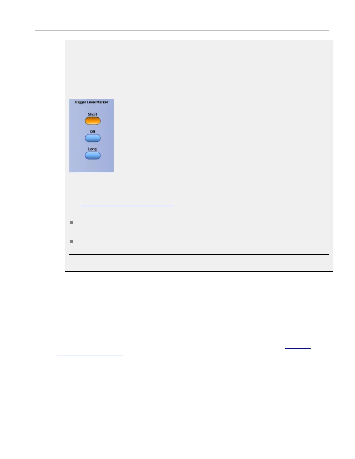
Trigger level marker
From the Display menu, select Objects, or open the Objects tab in the Display control window.
To use
Click one of the buttons to select the trigger level indicator.
Behavio
r
The trigger level markers (see page 637) indicate the v oltage level where the trigger o r threshold
levels
of the active waveform occur:
The Short trigger level marker displays a short arrow on the side of the graticule by the active
wavefo
rm.
The Long trigger level marker displays a horizontal line through the active waveform.
NOTE
. The trigger level indicator does not appear on inactive waveforms, reference waveforms,
or fast acquisition signals.
Set
up triggering from the Front Panel
Th
e front panel provides quick access to the most frequently used trigger controls. The trigger readout
shows you the state of the trigger system.
Th
e Slope, Coupling, and Source controls only apply to edge triggering. To access the advanced trigger
controls, open the Trigger Setup control window by pushing the Advanced button. (See Advanced
Triggering (see page 639) for more information.)
Use the following procedure to set up triggers using the front-panel controls:
DSA/DPO70000D, MSO/DPO/DSA70000C, DPO7000C, and MSO/DPO5000 Series 637
 Loading...

