Trigger setups Set up an I2C bus trigger
To use
Click the Trigger Type box and select Bus from the drop-down list.
Click the Bus box and select the bus number or name from the drop-down list.
NOTE. You have the option to add user-defined label for bus sources.
Click the Logic Thresholds Setup button to set the voltage threshold levels for the channels in the bus.
Select the type of bus cycle or activity to u se as the trigger from the Trigger On drop-down list.
For some Trigger On selections, you need to set additional fields to define other parameters such as
for an Address.
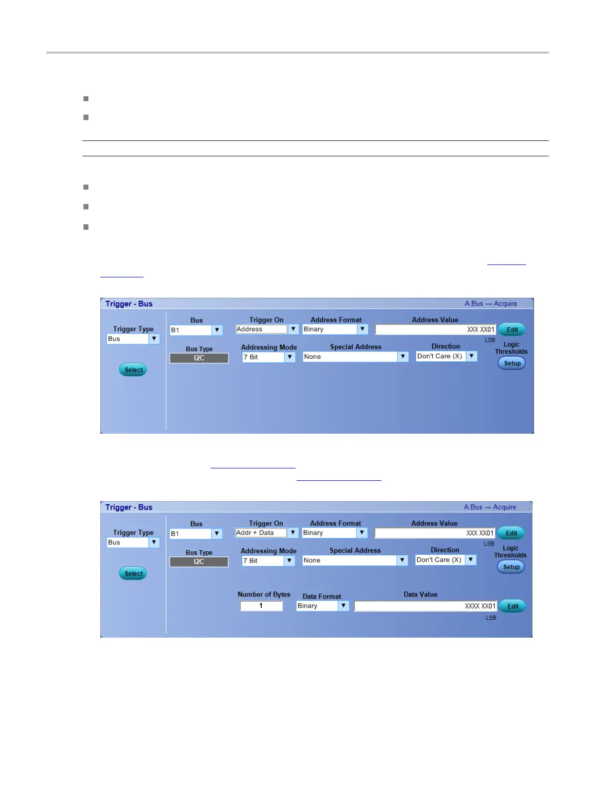
In the following example, you need to set an Address Format, Address Value (click the Edit
(see
page 938) button), Data Direction, and Addressing Mode. Optionally, you can also set the component
threshold levels through the Logic Thresholds Setup button.
In the following example on MSO/DPO5000 Series inst
ruments,youneedtosetanAddressFormat,
Address Value (click the Edit
(see page 939) button), Addressing Mode, Special Address, Direction,
Number of Bytes, Data Format, Data Value (Edit
(see page 939)) for the Addr+Data Trigger On type.
Optionally, you can also set the component threshold levels through the Logic Thresholds Setup button.
In DPO7000C and MSO70000C Series instruments, when you trigger on an Address for I2C serial
bus, there are some predefined patterns termed as Special Addresses. Use this information to debug
your serial bus. The following table lists the predefined patterns along with their names.
396 DSA/DPO70000D, MSO/DPO/DSA70000C, DPO7000C, and MSO/DPO5000 Series
 Loading...

