Oscilloscope Reference Logic pattern format
Logic pattern format
NOTE. This online help file supports many oscilloscope models from Tektronix. This feature is only
available on
some models.
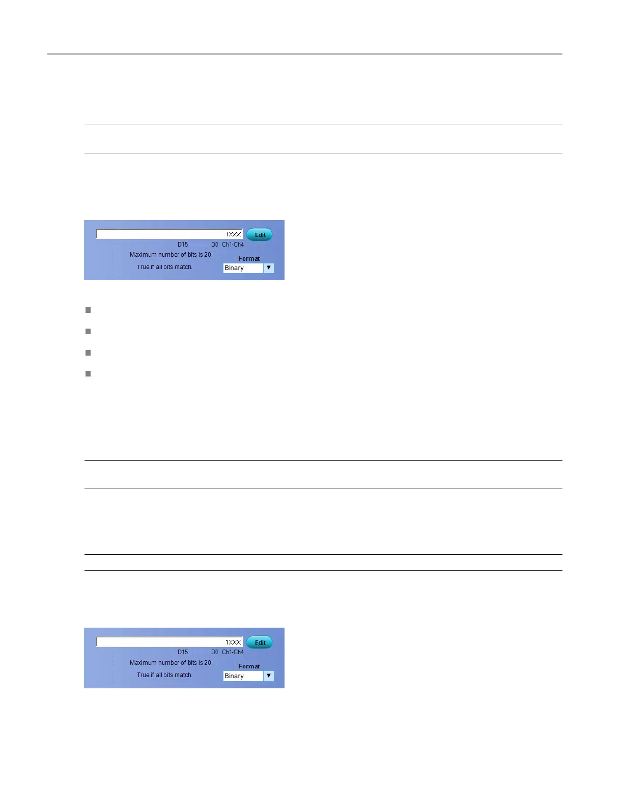
Select the Logic Pattern or Logic State trigger type. You can change the format of the pattern after you
define a logic pattern.
ASCII causes the instrument to represent the bus pattern value as an ASCII value.
Decimal cause s the instrument to represent the bus pattern value as a decimal value.
Hex causes the instrument to represent the bus pattern value as a hexadecimal value.
Binary causes the instrument to represent t he bus patte rn value as a binary value.
Logic pattern setup
NOTE. This online help file supports many oscilloscope models from Tektronix. This feature is only
available on some models.
Use the controls to set up the Logic Pattern or Logic State trigger pattern. ClicktheEditbuttontoaccess
the Pattern Editor dialog box.
NOTE. The Logic Pattern or Logic State trigger setups include the D15-D0 digital channels.
For information on the Pattern Editor dialog box, click the buttons.
850 DSA/DPO70000D, MSO/DPO/DSA70000C, DPO7000C, and MSO/DPO5000 Series
 Loading...

