Piston(Traction)PumpRemoval(Figure87)(continued)
3.Removedrainplugfromthehydraulicreservoiranddrainreservoirinto
asuitablecontainer.
4.Topreventcontaminationofhydraulicsystemduringremoval,thoroughly
cleanexteriorofpumpassembly.
g287906
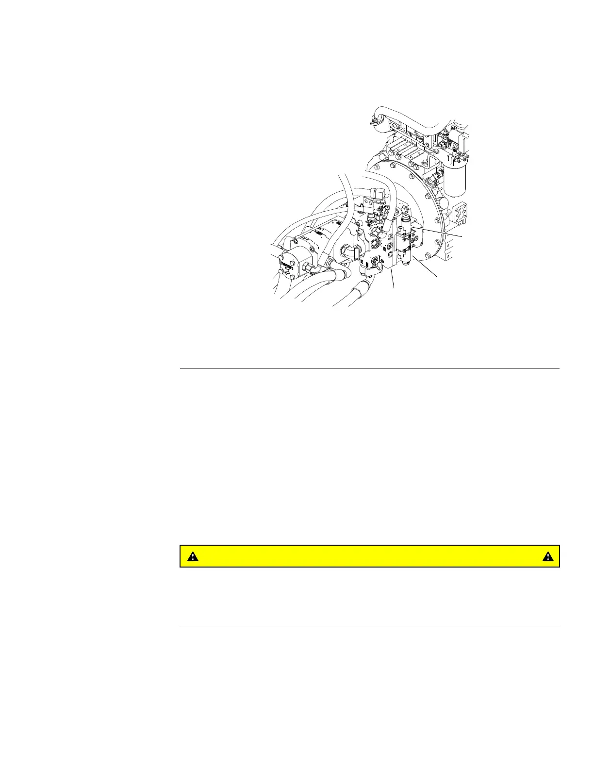
Figure88
1.Pistonpump
3.Reversesolenoidcoil(S2)
2.Forwardsolenoidcoil(S1)
5.Labelwireharnessconnectorsthatattachtothetwo(2)solenoidcoilson
leftsideofpistonpump(Figure88).Disconnectharnessconnectorsfrom
solenoidcoilsonpistonpump.
6.ReadtheGeneralPrecautionsforRemovingandInstallingHydraulicSystem
Components(page5–73).
7.Forinstallationpurposes,labelallhydrauliclinesthatconnecttogearpump
andpistonpump.
8.Putadrainpanbelowthepumpassembly.Removehydraulichoses
connectedtopistonandgearpumpttings.Putplugsorcapson
disconnectedhydraulichosesandttingstopreventcontaminationofthe
system.
9.Removegearpumpfrommachine(seeGearPump(page5–86)).
CAUTION
Makesurepistonpumpisproperlysupportedbeforeremoving
thepumpmountingscrews.Pistonpumpassemblyweighs
approximately51kg(110lb).
10.Attachhoisttopistonpumptosupportpumpandallowsaferemovalof
pumpfrommachine.
11.Removefour(4)capscrewsandwashersretainingpumpassemblytoengine
ywheelplate.Carefullypullpumpassemblyfromywheelplateandpump
adapterplate(coupler),thenlowerthepumpoutofthemachine.
Groundsmaster
®
5900&5910
Page5–95
HydraulicSystem:ServiceandRepairs
16227SLRevB
 Loading...


