ChargingSystemTests(continued)
g288427
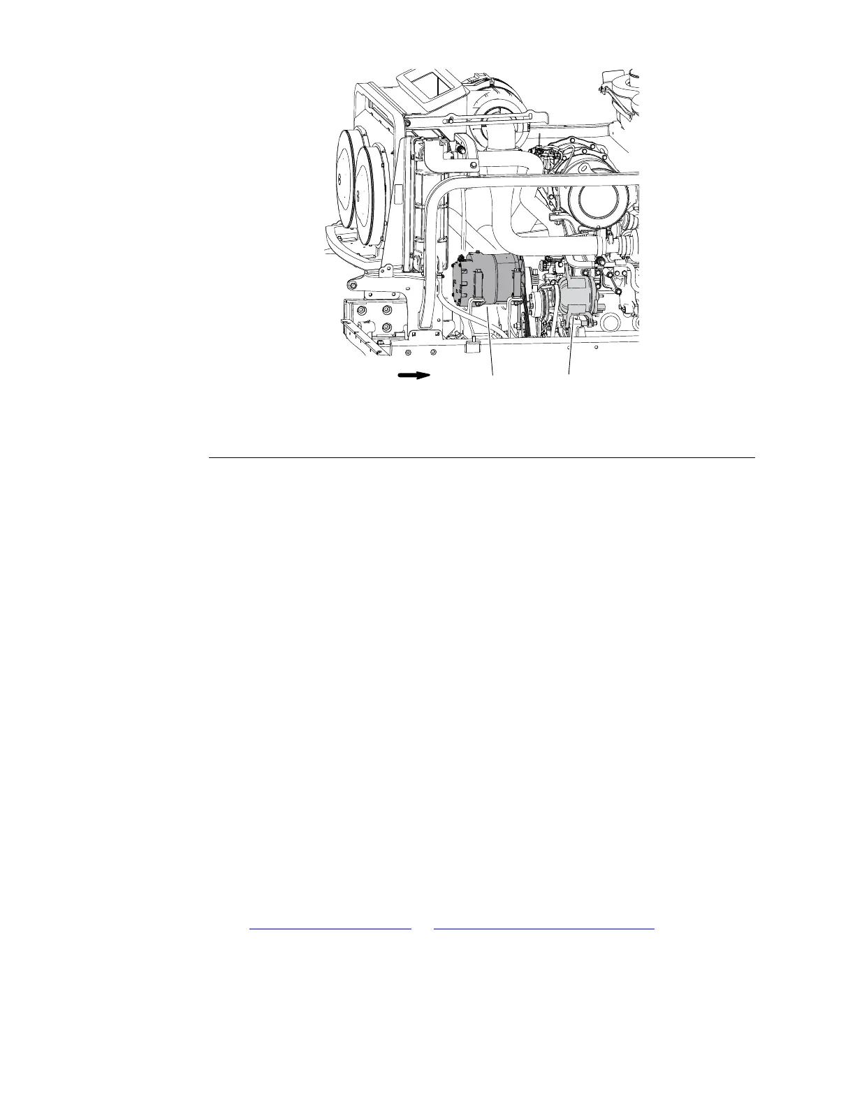
Figure186
1.12Voltalternator2.24Voltalternator
TheGroundsmaster5900/5910usesfour(4)12Voltmaintenancefreebatteries.
Twobatteriesareconnectedtogetherinparalleltosupportthe12Voltelectrical
systemandtwo(2)batteriesareconnectedtogetherinseriestosupportthe24
Voltcoolingfancircuit(Figure185).The12Voltsystemischargedbyan80Amp
12voltalternatormountedtotheengine,whichisdrivenbyasinglerowV-belt
(Figure186).The24Voltsystemischargedbyan105Amp24Voltalternator
mountedtotheframe,whichisdrivenbyamulti-rowV-belt.
UsetheInfoCenterdisplaytomonitorthe12Voltand24Voltsystems.Itwilltell
youifthedesiredchargingsystemhasanoutput,butnotitscapacity.
1.Checktomakesureeachalternatordrivebeltisnotloose,wornordamaged.
2.TurnthekeyswitchtotheRUNpositionandsettheInfoCenterdisplayto
viewthevoltmeter(seeInfo-CenterDisplay−OperatorInformationScreen
(page6–11)).
3.Recordtheinitialsystemvoltageforboththe12Voltand24Voltsystem.
4.Starttheengineandwarmtheenginetonormaloperatingtemperature.
5.SettheengineRPMto2000RPM.
12VoltSystemCheck:
•Turnonalladditional12Voltsystemloads(e.g.lights,heater/ACblower).
•The12Voltsystemvoltageshouldbeatleast0.5volthigherthenthe
initialvoltagerecordedinstep3.
•Ifthe12Voltchargingsystemperformanceislessthandesired,seethe
YanmarServiceManual
orYanmarTroubleshootingManualforadditional
information.
ElectricalSystem:InfoCenterDisplay
Page6–44
Groundsmaster
®
5900&5910
16227SLRevB
 Loading...


