Testing(continued)
4.Disconnectthemachinewireharnessconnectorfromtherelay.Remove
relayfrommountingbracketfortesting.
Note:Priortotakingsmallresistancereadingswithadigitalmultimeter,short
themetertestleadstogether.Themeterwilldisplayasmallresistancevalue
(usually0.5ohmsorless).Thisresistanceisduetotheinternalresistanceof
themeterandtestleads.Subtractthisvaluefromthemeasuredvaluefor
thetestedcomponent.
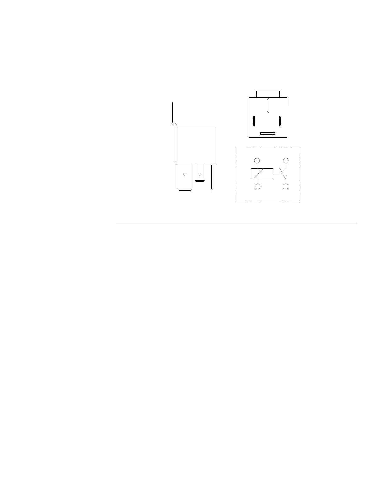
g288554
Figure243
5.Usingamultimeter(ohmssetting),measurecoilresistancebetweenterminals
85and86(Figure243).Resistanceshouldbebetween70and100ohms.
6.Verifyinniteresistance(nocontinuity)betweenterminals30and87.
7.Connectmultimeter(ohmssetting)leadstorelayterminals30and87.
Groundterminal86andapply+12VDCtoterminal85.Therelayshould
makeandbreakcontinuitybetweenterminals30and87as+12VDCis
appliedandremovedfromterminal85.
8.Disconnectmeterleadsandjumperwiresfromtherelayterminals.
Reconnectmachinewireharnessconnectortorelay.
9.Installandsecurepanelsandcoversremovedtoaccessrelays.
10.Turnthebattery−disconnectswitchtotheONpositionbeforereturningthe
machinetoservice.
Groundsmaster
®
5900&5910
Page6–101
ElectricalSystem:ComponentTesting
16227SLRevB
 Loading...


