JointYokeAssembly(continued)
g298933
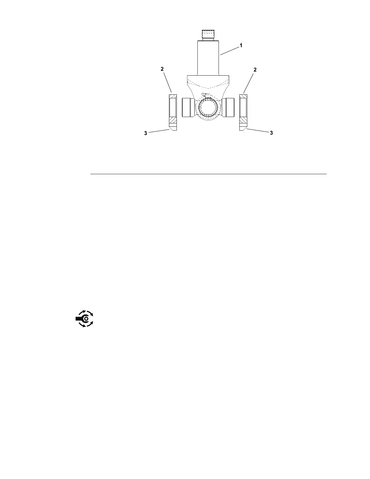
Figure309
1.Jointyoke3.Anglededge
2.Basemount
8.Pressbasemountsontobearingcapswiththeanglededgeofthemounts
awayfromthejoint(Figure309).Theoutsideofthecrossbearingcups
shouldbeushwiththebasemountsurfaces.
9.Makesurethatassembledjointyokemoveswithoutbinding.Slightbinding
canusuallybeeliminatedbylightlyrappingtheyokelugswithasoftfaced
hammer.Ifbindingcontinues,disassemblejointyoketoidentifyandeliminate
sourceofbinding.
JointYokeInstallation(Figure307andFigure308)
1.Installjointyoketoliftarm:
A.Placespacer(item7)andthenthrustwasherontojointyokeshaft.
B.Insertyokeshaftupthroughliftarmbushings.
C.Placethrustwasher(item6)ontojointyokeshaftandthenplace
washer(s)(item5)asneededtoremoveasmuchclearanceaspossible
betweenthethrustwasherandthehardenedwasher(item4).
D.Installslottedhexnuttosecurejointyoketoliftarm.T orquenutfrom
204to244N·m(150to180ft−lb).Makesurethatjointyokerotatesin
liftarmwithoutbindingandthatexcessiveclearancedoesnotexistin
yokeassembly.
2.Carefullylowerliftarmtopositionbasemountstodeckconnection.
3.Installshimsbetweendeckconnectionandbasemounts.Securebase
mountswitheight(8)capscrews,hardenedwashersandtwo(2)boltplates.
Tightencapscrewsfrom53to64N·m(39to47ft−lb).
4.Greasejointyokeandliftarmbushingafterinstallationonmachine.
5.Afterassemblyiscompleted,raiseandlowerthecuttingdecktoverifythat
hydraulichosesandttingsdonotcontactanythingthroughoutthefullrange
ofmovement.
Chassis:ServiceandRepairs
Page7–30
Groundsmaster
®
5900&5910
16227SLRevB
 Loading...


