July, 2007
2-15
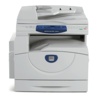
WorkCentre 5020
Status Indicator RAPS
Initial Issue
E5-1
Error Name
IOT L/H Cover open
Explanation
The Left Hand Cover is open.
I/O Diagnostic Codes (How to Enter the Diagnostic Mode)
[01-01] LH Cover Interlock Switch
Check Items
• Check that the Left Hand Cover closes correctly.
• Check that the LH Cover Interlock Switch is correctly installed and that the electrical connection is good.
• Check that the following wires are connected securely with good electrical contact. If there is no problem, replace the LH Cover Interlock
Switch (PL 8.2).
– Wire between LH Cover Interlock Switch FS151 ( FS151) and LVPS J506-4 ( P/J506)
– Wire between LH Cover Interlock Switch FS152 ( FS152) and LVPS J506-3
• Replace the LVPS (PL 8.1) (REP 8.1.2) and the AIOC PWB (PL 8.1) (REP 8.1.1) in that order.
X -
CH1.2
Figure 2
E5-2
Error Name
IOT Front Cover open
Explanation
The Front Cover is open.
I/O Diagnostic Codes (How to Enter the Diagnostic Mode)
[01-12] Front Cover Interlock Switch
Check Items
• Check that the Front Cover closes correctly.
• Check that the Front Cover Interlock Switch is correctly installed and that the electrical connection is good.
• Check that the following wires are connected securely with good electrical contact. If there is no problem, replace the Front Cover Interlock
Switch (PL 8.2).
– Wire between Front Cover Interlock Switch FS153 ( FS153) and LVPS J506-2 ( P/J506)
– Wire between Front Cover Interlock Switch FS154 ( FS154) and LVPS J506-1
• Replace the LVPS (PL 8.1) (REP 8.1.2) and the AIOC PWB (PL 8.1) (REP 8.1.1) in that order.
X -
CH1.2
Figure 2
E6-1
Error Name
L/H Low Cover open
Explanation
Access Cover 1 is open.
I/O Diagnostic Codes (How to Enter the Diagnostic Mode)
[01-11] Tray1 Interlock Switch
Check Items
• Check that Access Cover 1 closes correctly.
• Check that the Tray 1 Interlock Switch is correctly installed and that the electrical connection is good.
• Check that the following wires are connected securely with good electrical contact. If there is no problem, replace the Tray 1 Interlock
Switch (PL 2.5).
– Wire between Tray 1 Interlock Switch J161-2 ( P/J161) and LVPS J501-9 ( P/J501)
– Wire between Tray 1 Interlock Switch J161-1 and LVPS J501-10
• Replace the LVPS (PL 8.1) (REP 8.1.2) and the AIOC PWB (PL 8.1) (REP 8.1.1) in that order.
X -
CH7.1
Figure 1
Error
Code Error Name/Explanation/I/O Diagnostic Codes/Check Items
Record in
Error Log RAP BSD
 Loading...


