July, 2007
2-23
WorkCentre 5020
Status Indicator RAPS
Initial Issue
U4-9
Error Name
Fuser Fan defect
Explanation
After the start of Fan Fail Signal monitoring, the signal level was Low not more than 30 times.
O U4-9
CH10.3
Figure 3
U6-2
Error Name
RAM read/write check error
Explanation
When the MCU runs the overall Read/Write check for RAM during startup, the Read Data and Write Data do not match.
O U6-2
CH3.2
Figure 2
U6-3
Error Name
NVM data defect
Explanation
• The NVM Header data ERROR and NVM 3 page data do not match.
• Or, unable to find the NVM Write & Read area.
• The NVM or Counter areas are full.
O U6-3
CH3.2
Figure 2
U6-4
Error Name
NVM read/write cannot be executed
Explanation
• An NVM Ack NG is detected during NVM Read.
• An NVM Write Error is detected 5 times during NVM Recovery.
O U6-4
CH3.2
Figure 2
U6-5
Error Name
CPU Power to access NVM is not enough
Explanation
NVM queue full is detected during NVM Write.
O U6-5
CH3.2
Figure 2
U7-0
Error Name
UI Communication TimeOut
Explanation
At the Power On Sequence, the AIOC PWB did not communicate with the User Interface PWB.
X U7-0
CH2.1
Figure 1
U7-1
Error Name
UI Communication Error
Explanation
The User Interface PWB has detected a communication failure.
X U7-1
CH2.1
Figure 1
U8-1
Error Name
Billing Counter Defect
Explanation
• It is detected that the Billing Counter Value is incorrect.
• Or, the AOIC PWB has failed to read the Billing Counter.
O U8-1
CH3.2
Figure 2
U9-0
Error Name
HVPS fail
Explanation
A 500 msec cycle of the signal HVPS#ERR=High was detected twice in a row.
O U9-0
CH9.1
Figure 1
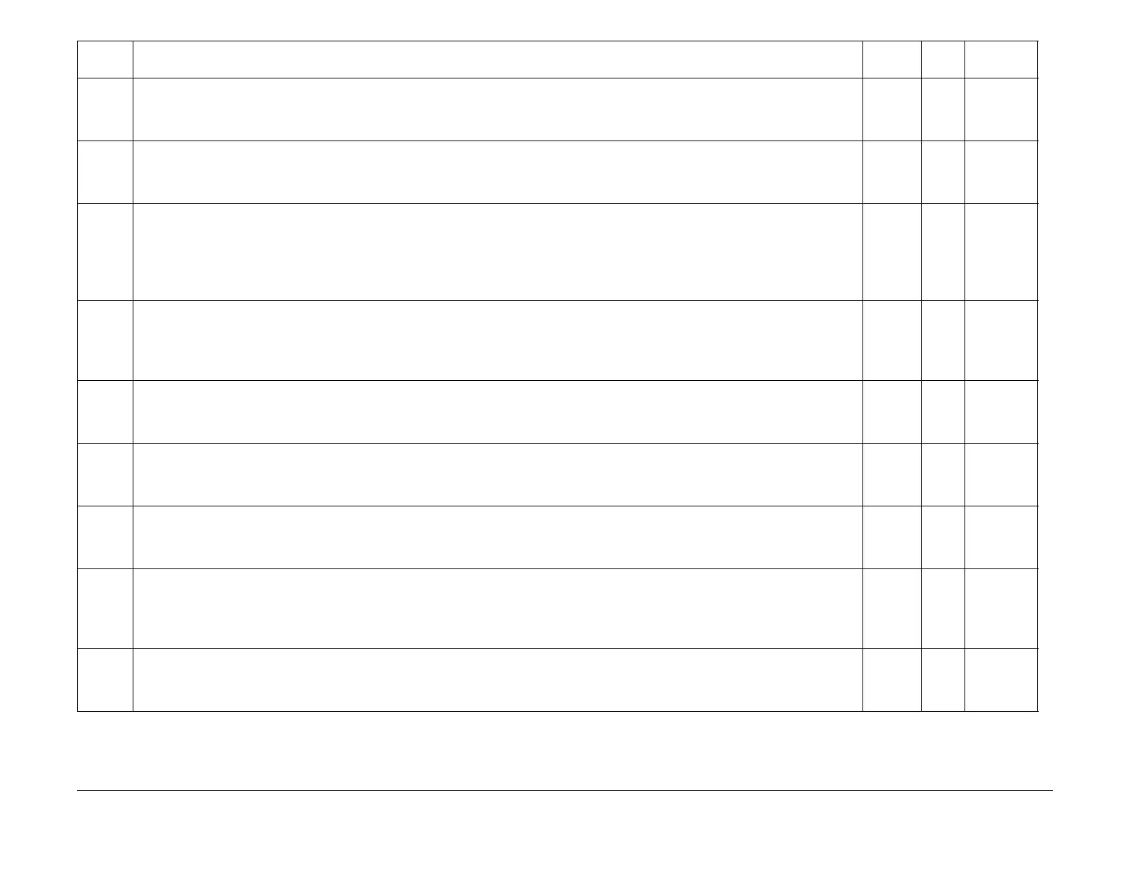
Error
Code Error Name/Explanation/I/O Diagnostic Codes/Check Items
Record in
Error Log RAP BSD

 Loading...