5.7 H: Terminal Functions
YASKAWA ELECTRIC SIEP C710616 35D YASKAWA AC Drive E1000 Technical Manual 205
◆ H4: Multi-Function Analog Outputs
These parameters assign functions to analog output terminals FM and AM for monitoring a specific aspect of drive
performance.
■
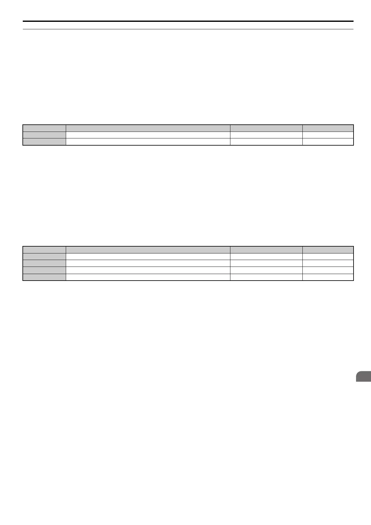
H4-01, H4-04: Multi-Function Analog Output Terminal FM, AM Monitor Selection
Sets the desired drive monitor parameter U- to output as an analog value via terminal FM and AM. Refer to U:
Monitor Parameters on page 253 for a list of all monitors. The “Analog Output Level” column indicates if a monitor can
be used for analog output.
Example: Enter “103” for U1-03.
A setting of 031 or 000 applies no drive monitor to the analog output. With this setting, terminal functions as well as FM
and AM output levels can be set by a PLC via a communication option or MEMOBUS/Modbus (through mode).
■
H4-02, H4-03: Multi-Function Analog Output Terminal FM Gain and Bias
H4-05, H4-06: Multi-Function Analog Output Terminal AM Gain and Bias
Parameter H4-02 and H4-05 set the terminal FM and AM output signal level equal to 100% of the monitor (gain).
Parameter H4-03 and H4-06 set the bias added to the monitor output for terminals FM and AM. Both are set as a
percentage, where 100% equals 10 Vdc analog output. The output voltage of both terminals is limited to 10 Vdc.
The output signal range can be selected between 0 to +10 Vdc or -10 to +10 Vdc using parameter H4-07 and H4-08.
Figure 5.58 illustrates how gain and bias settings work.
Using Gain and Bias to Adjust Output Signal Level
The output signal is adjustable while the drive is stopped.
Terminal FM
1. View the value set to H4-02 (Terminal FM Monitor Gain) on the digital operator. A voltage equal to 100% of the
parameter being set in H4-01 will be output from terminal FM.
2. Adjust H4-02 viewing the monitor connected to the terminal FM.
3. View the value set to H4-03 on the digital operator, terminal FM will output a voltage equal to 0% of the parameter
being set in H4-01.
4. Adjust H4-03 viewing the output signal on the terminal FM.
Terminal AM
1. View the value set to H4-05 (Terminal AM Monitor Gain) on the digital operator. A voltage equal to 100% of the
parameter being set in H4-04 will be output from terminal AM.
2. Adjust H4-05 viewing the monitor connected to the terminal AM.
3. View the value set to H4-06 on the digital operator, terminal AM will output a voltage equal to 0% of the parameter
being set in H4-04.
4. Adjust H4-06 viewing the output signal on the terminal AM.
Example 1: To have an output signal of 5 V at terminal FM when the monitored value is at 100%, set H4-02 to 50%.
Example 2: To have an output signal of 10 V at terminal FM when the monitored value is at 76.7%, set H4-02 to 150%.
No. Name Setting Range Default
H4-01 Multi-Function Analog Output Terminal FM Monitor Selection 000 to 999 102
H4-04 Multi-Function Analog Output Terminal AM Monitor Selection 000 to 999 103
No. Name Setting Range Default
H4-02 Multi-Function Analog Output Terminal FM Gain -999.9 to 999.9% 100.0%
H4-03 Multi-Function Analog Output Terminal FM Bias -999.9 to 999.9% 0.0%
H4-05 Multi-Function Analog Output Terminal AM Gain -999.9 to 999.9% 50.0%
H4-06 Multi-Function Analog Output Terminal AM Bias -999.9 to 999.9% 0.0%
SIEP_C710616_35.book 205 ページ 2015年11月30日 月曜日 午後2時2分