3.9 Control Circuit Wiring
YASKAWA ELECTRIC SIEP C710616 35D YASKAWA AC Drive E1000 Technical Manual 79
3.9 Control Circuit Wiring
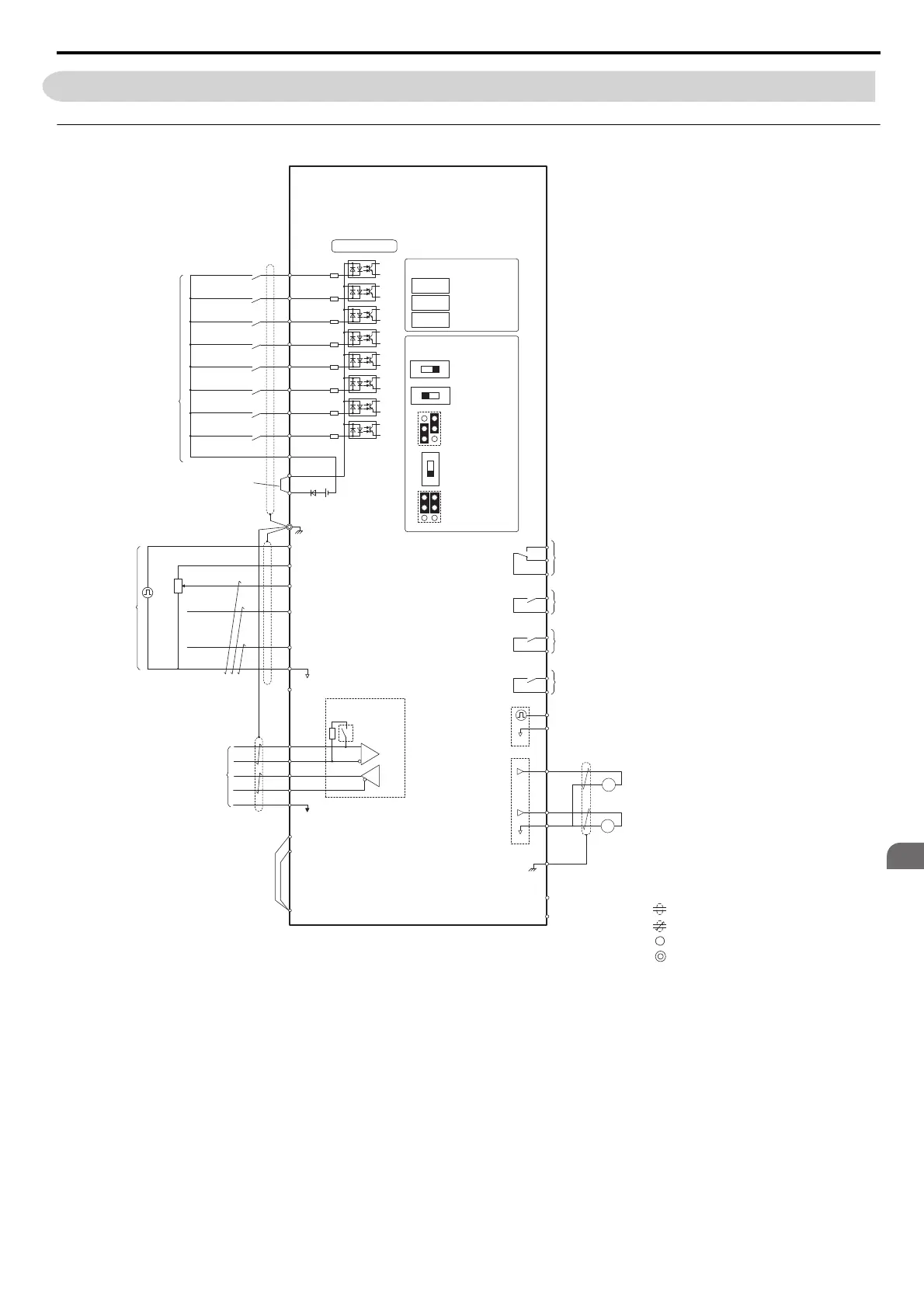
◆ Control Circuit Connection Diagram
Figure 3.29
Figure 3.22 Control Circuit Connection Diagram
<1> Supplying power to the control circuit separately from the main circuit requires 24 V power supply (option).
<2> This figure shows an example of a sequence input to S1 through S8 using a non-powered relay or an NPN transistor. Install the wire
link between terminals SC-SP for Sink mode and SC-SN for Source mode. Leave it out for external power supply. Never short
terminals SP and SN as doing so will damage the drive.
<3> The maximum current supplied by this voltage source is 150 mA.
<4> The maximum output current capacity for the +V and -V terminals on the control circuit is 20 mA. Never short terminals +V, -V, and
AC, as this can cause erroneous operation or damage the drive.
<5> Set DIP switch S1 to select between a voltage or current input signal to terminal A2. The default setting is for current input.
<6> Set DIP switch S4 to select between analog or PTC input for terminal A3.
<7> Enable the termination resistor in the last drive in a MEMOBUS network by setting DIP switch S2 to the ON position.
<8> Monitor outputs work with devices such as analog frequency meters, ammeters, voltmeters, and wattmeters. They are not intended for
use as a feedback-type of signal.
Drive
+
+
+
+
+
−
S1
S2
S3
S4
S5
S6
S7
MP
RP
A
1
A2
A3
0
V
AC
R
R
S
S
IG
2 kΩ
S8
SC
0 V
0 V
AC
FM
AM
AC
E (G)
<4>
<8>
<8>
<5>
<7>
<4>
<2>
<1>
+
24 V
+V
MA
M
1
M2
MB
MC
Forward Run / Stop
Reverse Run / Stop
External fault
Fault reset
Multi-step speed 1
Multi-step speed 2
External Baseblock
Jog speed
Multi-function
digtial inputs
(default setting)
Sink / Source mode
selection wire link
(default: Sink)
CN5-A
CN5-B
CN5-C
Option card connectors
Pulse Train Input (max 32 kHz)
Shield ground terminal
Multi-function
analog/ pulse
train inputs
Power supply +10.5 Vdc, max. 20 mA
Analog Input 1 (Frequency Reference Bias)
-10 to +10 Vdc (20 k
Ω
)
Analog Input 2 (Frequency Reference Bias)
-10 to +10 Vdc (20 k
Ω
)
0 or 4 to 20 mA (250
Ω
)
Analog Input 3 / PTC Input (Aux. frequency
reference)
-10 to +10 Vdc (20 k
Ω
)
−V
Power supply, -10.5 Vdc, max. 20 mA
MEMOBUS/Modbus
comm. RS-422/RS-485
max. 115.2 kBps
Termination resistor
(120
Ω
, 1/2 W)
DIP
Switch S2
Fault relay output
250 Vac, max. 1 A
30 Vdc, max 1 A
(min. 5 Vdc, 10 mA)
Multi-function relay output (During Run)
250 Vac, max. 1 A
30 Vdc, max 1 A
(min. 5 Vdc, 10 mA)
Multi-function pulse train output
(Output frequency)
0 to 32 kHz (2.2 k
Ω
)
Multi-function analog output 1
(Output frequency)
-10 to +10 Vdc (2mA) or 4 to 20 mA
Multi-function analog output 2
(Output current)
-10 to +10 Vdc (2mA) or 4 to 20 mA
Control Circuit
M3
M4
Multi-function relay output (Zero Speed)
250 Vac, max. 1 A
30 Vdc, max 1 A
(min. 5 Vdc, 10 mA)
M5
M6
Multi-function relay output (Speed Agree 1)
250 Vac, max. 1 A
30 Vdc, max 1 A
(min. 5 Vdc, 10 mA)
SP
SN
<6>
AMFM
V
I
V
I
DIP Switch S1
A2 Volt/Curr. Sel
DIP Switch S4
A3 Analog/PTC
Input Sel
PTC
AI
Off
On
DIP Switch S2
Term. Res. On/Off
Jumper S5
AM/FM Volt./Curr.
Selection
Terminal board
jumpers and switches
FM
+
−
AM
<3>
shielded line
twisted-pair shielded line
main circuit terminal
control circuit terminal
+
−
+
−
DM
DM
H
1
H2
HC
<10>
<9>
<11>
Wire
jumper
Hardwire Baseblock monitor
Jumper S3
Terminal H1/H2
Sink/Source
Selection
SIEP_C710616_35.book 79 ページ 2015年11月30日 月曜日 午後2時2分