B.3 Parameter Table
388 YASKAWA ELECTRIC SIEP C710616 35D YASKAWA AC Drive E1000 Technical Manual
◆ o: Operator Related Settings
The o parameters are used to set up the digital operator displays.
■
o1: Digital Operator Display Selection
n8-51
(53EH)
Acceleration/Deceleration Pull-In
Current
Sets the d-axis current reference during acceleration/deceleration as a percentage of the motor
rated current. Set to a high value when more starting torque is needed.
Default: 50%
Min: 0%
Max: 200%
244
n8-54
(56DH)
Voltage Error Compensation Time
Constant
Adjusts the value when hunting occurs at low speed. If hunting occurs with sudden load
changes, increase n8-54 in increments of 0.1. Reduce this setting if oscillation occurs at start.
Default: 1.00 s
Min: 0.00 s
Max: 10.00 s
244
n8-55
(56EH)
Load Inertia
Sets the ratio between motor and machine inertia.
0: less than 1:10.
1: between 1:10 to 1:30.
2: between 1:30 to 1:50.
3: higher than 1:50.
Default: 0
Min: 0
Max: 3
244
n8-62
(57DH)
<18>
Output Voltage Limit
Prevents output voltage saturation. Should be set just below the voltage provided by the input
power supply.
Default: 200.0 V
Min: 0.0 V
Max: 230.0 V
244
n8-65
(65CH)
Speed Feedback Detection Control
Gain during ov Suppression
Sets the gain used for internal speed feedback detection during ov suppression
Default: 1.50
Min: 0.00
Max: 10.00
245
<14> Default setting value is dependent on the motor code set to E5-01.
<18> Values shown here are for 200 V class drives. Double the value when using a 400 V class drive.
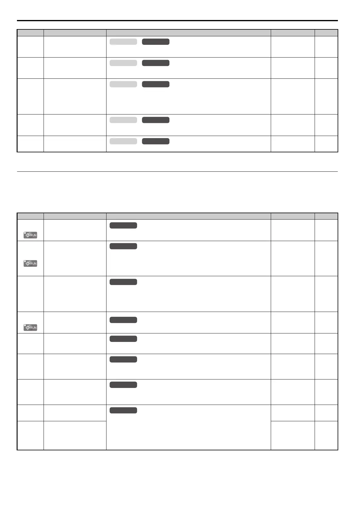
No. (Addr.) Name Description Setting Page
o1-01
(500H)
<10> Default setting is determined by the control mode (A1-02).
<36> Default setting value is determined by the digital operator display selection (o1-03).
Drive Mode Unit Monitor
Selection
Selects the content of the last monitor that is shown when scrolling through Drive Mode
display. Enter the last three digits of the monitor parameter number to be displayed: U-.
Default: 106 (Monitor
U1-06)
Min: 105
Max: 825
246
o1-02
(501H)
User Monitor Selection after
Power Up
1: Frequency reference (U1-01)
2: Motor direction
3: Output frequency (U1-02)
4: Output current (U1-03)
5: User-selected monitor (set by o1-01)
Default: 1
Min: 1
Max: 5
246
o1-03
(502H)
Digital Operator Display Selection
Sets the units the drive should use to display the frequency reference and motor speed monitors.
0: 0.01 Hz units
1: 0.01% units (100% = E1-04)
2: r/min units (calculated using the number of motor poles setting in E2-04, or E5-04)
3: User-selected units (set by o1-10 and o1-11)
Default:
<10>
Min: 0
Max: 3
246
o1-05
(504H)
LCD Contrast Control
Sets the brightness of the LCD operator (option).
Default: 3
Min: 0
Max: 5
247
o1-06
(517H)
User Monitor Selection Mode
0: 3 Monitor sqeuncial (Displays the next 2 sequencial Monitor)
1: 3 Monitor Selectable: o1-07,-08 selected monitor is shown
Default: 0
Min: 0
Max: 1
247
o1-07
(518H)
Second Line Monitor Selection
Selects which monitor will be displayed in the second line.
The monitor parameter number is entered into the spaces provided: U-.
For example, set "403" to display monitor parameter U4-03.
Default: 102
Min: 101
Max: 825
247
o1-08
(519H)
Third Line Monitor Selection
Selects which monitor will be displayed in the second line.
The monitor parameter number is entered into the spaces provided: U-.
For example, set "403" to display monitor parameter U4-03.
Default: 103
Min: 101
Max: 825
247
o1-10
(520H)
User-Set Display Units Maximum
Va lu e
These settings define the display values when o1-03 is set to 3.
o1-10 sets the display value that is equal to the maximum output frequency.
o1-11 sets the position of the decimal position.
0: No decimal point
1: One decimal point
2: Two decimal points
3: Three decimal points
Default:
<36>
Min: 1
Max: 60000
247
o1-11
(521H)
User-Set Display Units Decimal
Display
Default:
<36>
Min: 0
Max: 3
247
No. (Addr.) Name Description Setting Page
All Modes
All Modes
All Modes
All Modes
All Modes
All Modes
All Modes
All Modes
SIEP_C710616_35.book 388 ページ 2015年11月30日 月曜日 午後2時2分