5.5 E: Motor Parameters
174 YASKAWA ELECTRIC SIEP C710616 35D YASKAWA AC Drive E1000 Technical Manual
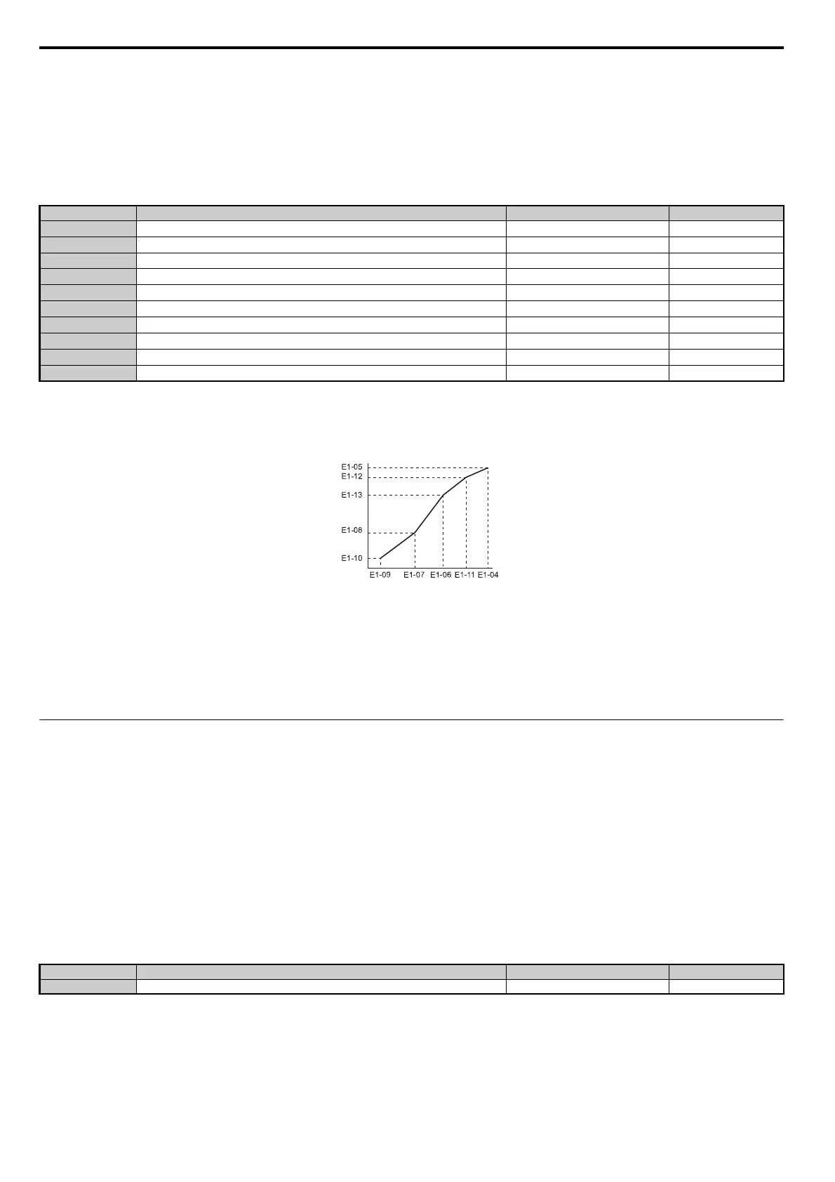
■ E1-04 to E1-13: V/f Pattern Settings
If E1-03 is set to a preset V/f pattern (i.e., set to any value besides F), then the user can refer to parameters E1-04 through
E1-13 to monitor the V/f pattern. To create a new V/f pattern, set E1-03 to F. Refer to Figure 5.29 for an example custom
V/f pattern.
Note: Certain E1- parameters might not be visible depending on the selected control mode. Refer to Parameter Table on page 360
for details.
Figure 5.29
Figure 5.29 V/f Pattern
Note: 1. The following condition must be true when setting up the V/f pattern: E1-09 ≤ E1-07 < E1-06 ≤ E1-11 ≤ E1-04
2. To make the V/f pattern a straight line below E1-06, set E1-09 = E1-07. In this case the E1-08 setting is disregarded.
3. E1-03 is unaffected when the parameters are initialized using parameter A1-03, but the settings for E1-04 through E1-13 are returned
to their default values.
4. Parameters E1-11, E1-12, and E1-13 should only be used to fine-tune the V/f pattern in the constant output range. These parameters
rarely need to be changed.
◆ E2: Motor Parameters
These parameters contain the motor data. They are set automatically when Auto-Tuning is performed (this includes
Rotational Auto-Tuning, Stationary Auto-Tuning 1 and 2). If Auto-Tuning cannot be performed, then manually enter the
motor data directly to these parameters.
Note: As the motor parameters for a PM motor are set up in the E5- parameters, parameters for induction motors (E2-) are
hidden when a PM motor control mode is selected for motor 1 (when A1-02 is set to 5).
■ E2-01: Motor Rated Current
Provides motor control, protects the motor, and calculates torque limits. Set E2-01 to the full load amps (FLA) stamped
on the motor nameplate. If Auto-Tuning completes successfully, the value entered to T1-04 will automatically be saved
to E2-01.
Note: 1. This value's number of decimal places depends on the drive model. The value will have two decimal places (0.01 A) if the drive is set
for a Maximum Applicable Motor Capacity up to 11 kW (refer to Table A.1 and Table A.2) and one decimal place (0.1 A) if the set
Maximum Applicable Motor Capacity is higher than 11 kW.
2. If the motor rated current in E2-01 is set lower than the motor no-load current in E2-03, than a parameter setting error will occur
(oPE02). E2-03 must be set correctly to prevent this error.
No.
<1> Default setting is determined by the control mode.
<2> When using PM motors, the default setting is determined by the motor code set to E5-01.
<3> Values shown here are for 200 V class drives. Double values when using a 400 V class unit.
<4> Parameter ignored when E1-11 and E1-12 are set to 0.0.
Parameter Name Setting Range Default
E1-04
Maximum Output Frequency
40.0 to 200.0 Hz <1> <2>
E1-05
Maximum Voltage
0.0 to 255.0 V <3> <1> <3>
E1-06
Base Frequency 0.0 to [E1-04]
<1> <2>
E1-07
Middle Output Frequency 0.0 to [E1-04]
<1>
E1-08
Middle Output Frequency Voltage
0.0 to 255.0 V <3> <1> <3>
E1-09
Minimum Output Frequency 0.0 to [E1-04]
<1> <2>
E1-10
Minimum Output Frequency Voltage
0.0 to 255.0 V <3> <1> <3>
E1-11
Middle Output Frequency 2 0.0 to [E1-04]
0.0 Hz <4>
E1-12
Middle Output Frequency Voltage 2
0.0 to 255.0 V <3> 0.0 V <3> <4>
E1-13
Base Voltage
0.0 to 255.0 V <3> 0.0 V <3>
No. Parameter Name Setting Range Default
E2-01 Motor Rated Current 10% to 200% of the drive rated current. Determined by o2-04
Output Voltage (V)
Frequency (Hz)
SIEP_C710616_35.book 174 ページ 2015年11月30日 月曜日 午後2時2分