4.7 Auto-Tuning
114 YASKAWA ELECTRIC SIEP C710616 35D YASKAWA AC Drive E1000 Technical Manual
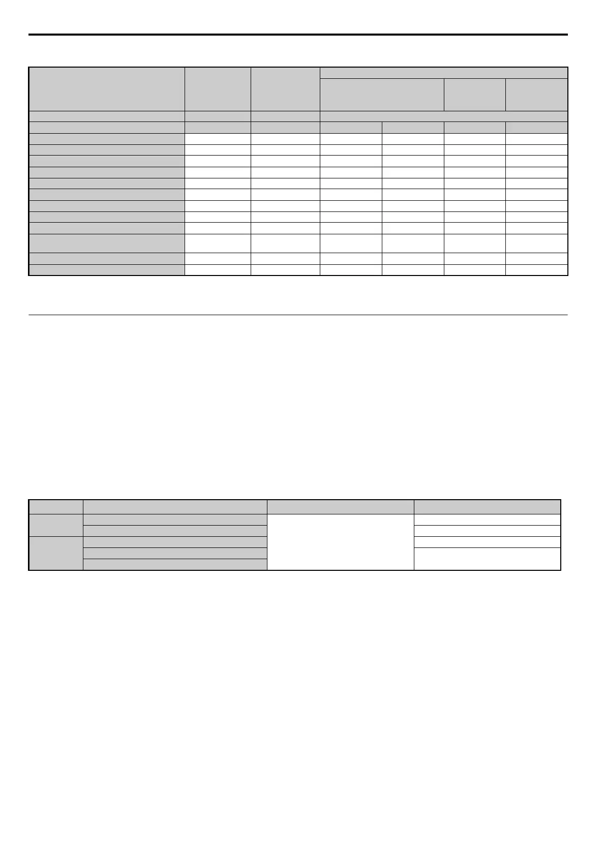
Table 4.16 Auto-Tuning Input Data
◆ Before Auto-Tuning the Drive
Check the items below before Auto-Tuning the drive.
■
Basic Auto-Tuning Preparations
• Auto-Tuning requires the user to input data from the motor nameplate or motor test report. Make sure this data is
available before Auto-Tuning the drive.
• For best performance, the drive input supply voltage must be greater than the motor rated voltage.
Note: Better performance is possible when using a motor with a base voltage that is 20 V (40 V for 400 V class models) lower than the
input supply voltage.
• To cancel Auto-Tuning, press the STOP key on the digital operator.
• When using a motor contactor, make sure it is closed throughout the Auto-Tuning process.
• Table 4.17 describes digital input and output terminal operation while Auto-Tuning is executed.
Table 4.17 Digital Input and Output Operation During Auto-Tuning
■ Notes on Rotational Auto-Tuning
• To achieve optimal performance from Rotational Auto-Tuning, the load should be decoupled from the motor.
Rotational Auto-Tuning is best suited for applications requiring high performance over a wide speed range.
• If motor and load can not be decoupled, reduce the load so that it is no greater than 30% of the rated load. Performing
Rotational Auto-Tuning with a higher load will set motor parameters incorrectly, and can cause irregular motor
rotation.
• Ensure the motor-mounted brake is fully released if installed.
• Connected machinery should be allowed to rotate the motor.
■
Notes on Stationary Auto-Tuning
Stationary Auto-Tuning modes analyze motor characteristics by injecting current into the motor for about one minute.
WARNING! Electrical Shock Hazard. When executing stationary Auto-Tuning, the motor does not rotate, however, power is applied.
Do not touch the motor until Auto-Tuning is completed. Failure to comply may result in injury from electrical shock.
WARNING! Sudden Movement Hazard. If installed, do not release the mechanical brake during stationary Auto-Tuning. Inadvertent
brake release may cause damage to equipment or injury to personnel. Ensure that the mechanical brake release circuit is not
controlled by the drive multi-function digital outputs.
Input Value
<1> Only parameter T2-13 or T2-14 has to be input. Select one and leave the other empty.
<2> Depends on T2-13 setting.
Input Parameter Unit
Tuning Type (T2-01)
0
Motor Parameter Settings
1
Stationary
2
Stationary
Stator
Resistance
Control Mode A1-02 – 5
Motor Code T2-02 – FFFFH FFFFH – –
Motor Type T2-03 – N/A N/A YES N/A
Motor rated power T2-04 kW N/A YES YES N/A
Motor rated voltage T2-05 Vac N/A YES YES N/A
Motor rated current T2-06 A N/A YES YES YES
Motor rated frequency T2-07 Hz N/A YES YES N/A
Number of motor poles T2-08 – N/A YES YES N/A
Stator 1 Phase resistance T2-10 Ω YES YES N/A N/A
d-axis inductance T2-11 mH YES YES N/A N/A
q-axis inductance T2-12 mH YES YES N/A N/A
Induced Voltage constant Unit
Selection
<1>
T2-13 mVs/rad (el.) YES YES N/A N/A
Voltage constant <2> T2-14 mVmin (mech.) YES YES N/A N/A
Tuning pull-in current T2-15 A N/A N/A YES N/A
Motor Type Auto-Tuning Type Digital Input Digital Output
IM Motor
Stationary Auto-Tuning for Line-to-Line Resistance
Digital input functions are disabled.
Maintains the status at the start of Auto-Tuning
Rotational Auto-Tuning for V/f Control Functions the same as during normal operation
PM Motor
PM Motor Parameter Settings Digital output functions are disabled.
PM Stationary Auto-Tuning
Maintains the status at the start of Auto-Tuning
PM Stationary Auto-Tuning for Stator Resistance
SIEP_C710616_35.book 114 ページ 2015年11月30日 月曜日 午後2時2分