5.7 H: Terminal Functions
206 YASKAWA ELECTRIC SIEP C710616 35D YASKAWA AC Drive E1000 Technical Manual
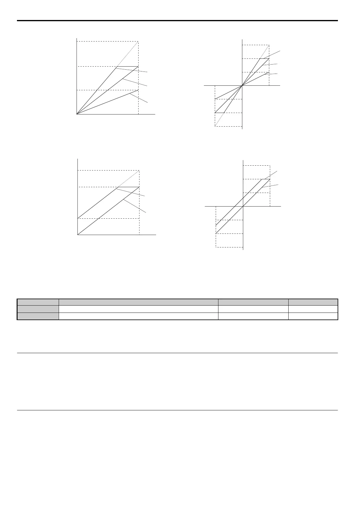
Figure 5.58
Figure 5.58 Analog Output Gain and Bias Setting Example 1 and 2
Example 3: To have an output signal of 3 V at terminal FM when the monitored value is at 0%, set H4-03 to 30%.
Figure 5.59
Figure 5.59 Analog Output Gain and Bias Setting Example 3
■ H4-07, H4-08: Multi-Function Analog Output Terminal FM, AM Signal Level Selection
Sets the voltage output level of U parameter (monitor parameter) data to terminal FM and terminal AM using parameters
H4-07 and H4-08.
Setting 0: 0 to 10 V
Setting 1: -10 V to 10 V
Setting 2: 4 to 20 mA
◆ H5: MEMOBUS/Modbus Serial Communication
Through the drives built in RS-422/RS-485 port (terminals R+, R-, S+, S-), serial communication is possible using
programmable logic controllers (PLCs) or similar devices running the MEMOBUS/Modbus protocol.
The H5- parameters are used to set up the drive for MEMOBUS/Modbus Communications. Refer to MEMOBUS/
Modbus Serial Communication on page 416 for detailed descriptions of the H5- parameters.
◆ H6: Pulse Train Input/Output
A one track pulse train signal with a maximum frequency of 32 kHz can be input to the drive at terminal RP. This pulse
train signal can be used as the frequency reference, for PI functions, or as the speed feedback signal in V/f Control.
The pulse output monitor terminal MP can output drive monitor values as a pulse train signal with a maximum frequency
of 32 kHz. It can be used in sinking or sourcing mode. Refer to Using the Pulse Train Output on page 87 for details.
Use parameters H6- to set the scale and other aspects of the pulse input terminal RP and pulse output terminal MP.
No. Name Setting Range Default
H4-07
Multi-Function Analog Output Terminal FM Signal Level Selection
0 to 2 0
H4-08
Multi-Function Analog Output Terminal AM Signal Level Selection
0 to 2 0
Output Voltage
Output Voltage
0 V
5 V
10 V
Gain 150%
Bias 0%
Gain = 150%
Bias = 0%
Gain = 100%
Bias = 0%
Gain = 50%
Bias = 0%
Gain 100%
Bias 0%
Gain 50%
Bias 0%
100%
Monitor Value
Monitor Value
0%
H4-07, 08 = 0 H4-07, 08 = 1
10V
-10 V
100%
5 V
15V
-5 V
-15 V
-100%
Gain = 100%
Bias = 30%
Gain = 100%
Bias = 0%
Gain 100%
Bias 30%
Gain 100%
Bias 0%
Monitor Value
Monitor Value
0 V
3 V
10 V
100%0%
Output Voltage
Output Voltage
H4-07, 08 = 0 H4-07, 08 = 1
10V
-10 V
100%
5 V
15 V
-5 V
-15 V
-100%
SIEP_C710616_35.book 206 ページ 2015年11月30日 月曜日 午後2時2分