2.2 Mechanical Installation
46 YASKAWA ELECTRIC SIEP C710616 35D YASKAWA AC Drive E1000 Technical Manual
When drives with IP20/NEMA 1, UL Type 1 enclosures are mounted side by side, the top protective covers of all drives
must be removed as shown in Figure 2.4. Refer to Top Protective Cover on page 71 to remove and reattach the top
protective cover.
Figure 2.4
Figure 2.4 IP20/NEMA 1, UL Type 1 Side-by-Side Mounting in Enclosure
◆ Instructions on Installation of Models CIMR-E4A0930 and 4A1200
Read the following precautions and instructions before installing the largest-capacity models, 4A0930 and 4A1200.
WARNING! Be sure to observe the following instructions and precautions. Failure to comply could result in minor or moderate injury
and damage to the drive from falling equipment.
• Vertical suspension of the drive should be used only for temporarily lifting the drive for installation in the enclosure
panel. Do not vertically suspend for transportation of the drive.
• Before vertical suspension, make sure that the drive front cover, terminal blocks and other drive components are
securely fixed with screws.
• Do not subject the drive to vibration or impact greater than 1.96 m/s
2
(0.2 G) while it is suspended by the wires.
• Do not overturn the drive.
• Do not leave the drive for a long time while it is suspended by the wires.
■
Procedure for Vertical Wire Suspension of the Drive
• Use the wire of a length that ensures a 50 degree or wider suspending angle, as illustrated in Figure 2.6. The maximum
allowable load of the eye bolts for suspension cannot be guaranteed when the drive is suspended with the wires at an
angle less than 50 degrees.
• When lifting the drive with a crane after wires are passed to hold it, make sure to follow the procedure described below.
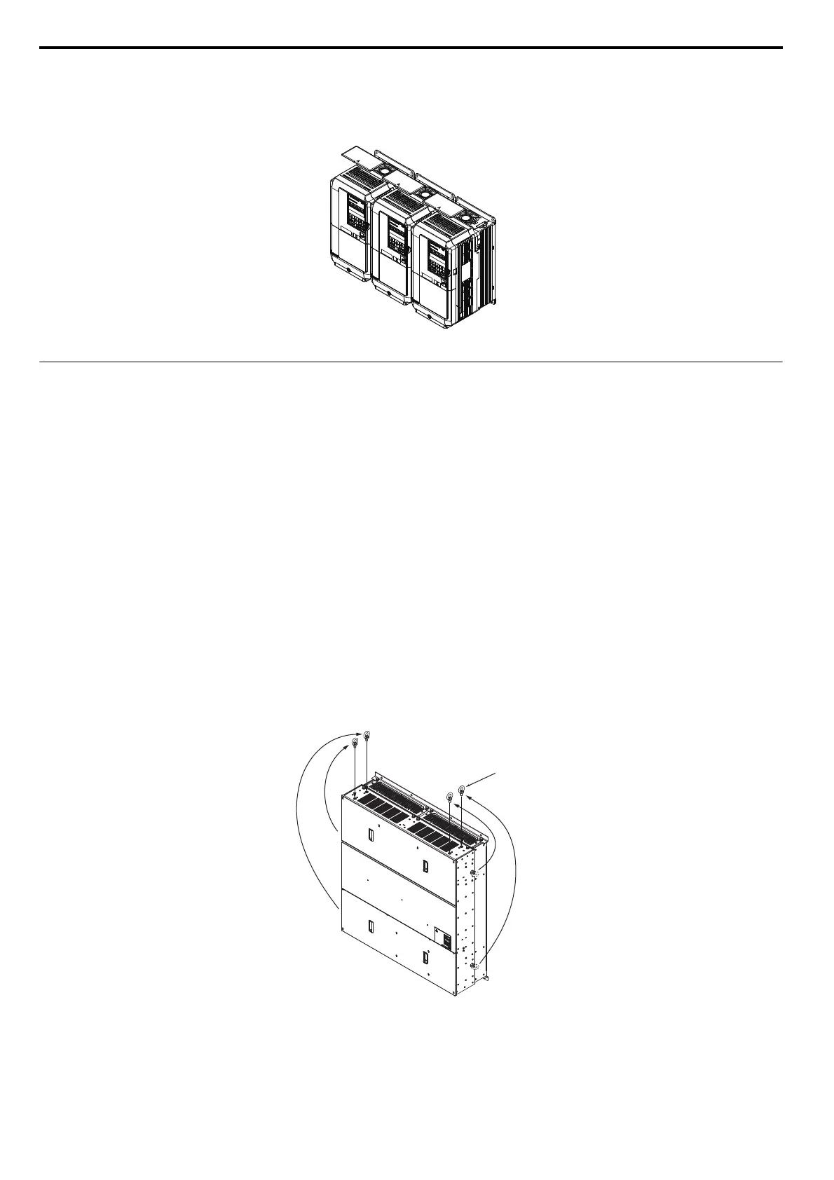
1. Remove the four eye bolts from the drive side panels, and fix them securely on the top panel (See Figure 2.5.).
Figure 2.5
Figure 2.5 Attaching Eye Bolts on Top Panel
Eye bolt
SIEP_C710616_35.book 46 ページ 2015年11月30日 月曜日 午後2時2分