3.3 Main Circuit Configurations
YASKAWA ELECTRIC SIEP C710616 35D YASKAWA AC Drive E1000 Technical Manual 61
3.3 Main Circuit Configurations
Refer to the Table 3.1 when wiring the drive’s main circuit. Connections may vary based on drive capacity. The DC
power supply for the main circuit also provides power to the control circuit.
NOTICE: Do not use the negative DC bus terminal “-” as a ground terminal. This terminal is at high DC voltage potential. Improper
wiring connections could damage the drive.
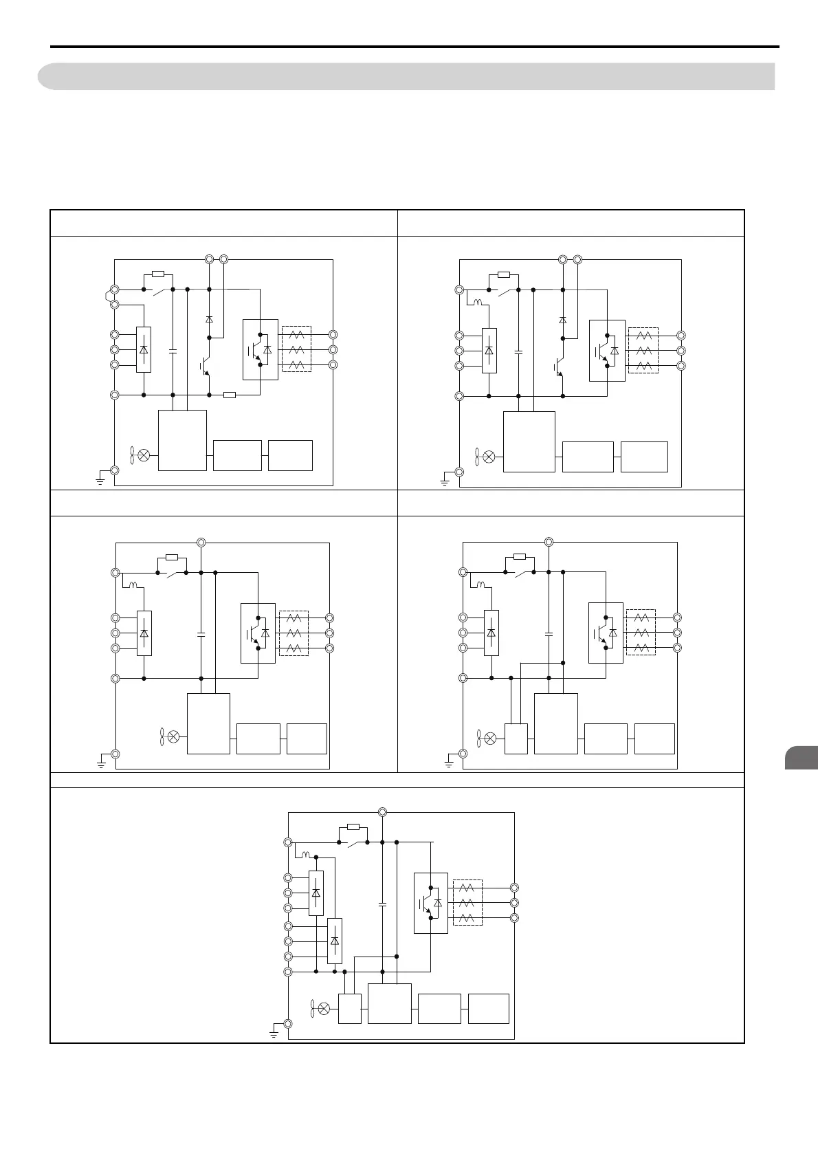
Table 3.1 Drive main circuit configurations
CIMR-E2A0004 to 2A0081
CIMR-E4A0002 to 4A0044
<1> Models CIMR-E4A0930 and 4A1200 are compatible for operation with 12-phase rectification. Refer to 12-Phase Rectification on
page 62 for details.
CIMR-E2A0110, 2A0138
CIMR-E4A0058, 4A0072
Figure 3.2 Figure 3.5
CIMR-E2A0169, 2A0211
CIMR-E4A0088 to 4A0139
CIMR-E2A0250 to 2A0415
CIMR-E4A0165 to 4A0675
Figure 3.3 Figure 3.6
CIMR-E4A0930, 4A1200 <1>
Figure 3.4
+1
+2
–
R/L1
S/L2
T/L3
Relay
Gate board
Control
board
Operator
+
Jumper
Current
sensor
U/T1
V/T2
W/T3
B1 B2
+1
–
R/L1
S/L2
T/L3
U/T1
V/T2
W/T3
B1 B2
DC
reactor
+
Relay
Gate board
Control
board
Operator
Current
sensor
+1
–
R/L1
S/L2
T/L3
U/T1
V/T2
W/T3
+
+3
DC
reactor
Relay
Gate board
Control
board
Operator
Current
sensor
+1
–
R/L1
S/L2
T/L3
U/T1
V/T2
W/T3
+3
+
24 V
Power
Supply
DC
reactor
Relay
Gate board
Control
board
Operator
Current
sensor
+1
–
R/L1
S/L2
T/L3
R1/L11
S1/L21
T1/L31
U/T1
V/T2
W/T3
+3
+
24 V
Power
Supply
DC
reactor
Relay
Gate board
Control
board
Operator
Current
sensor
SIEP_C710616_35.book 61 ページ 2015年11月30日 月曜日 午後2時2分