B.2 Parameter Groups
YASKAWA ELECTRIC SIEP C710616 35D YASKAWA AC Drive E1000 Technical Manual 359
B.2 Parameter Groups
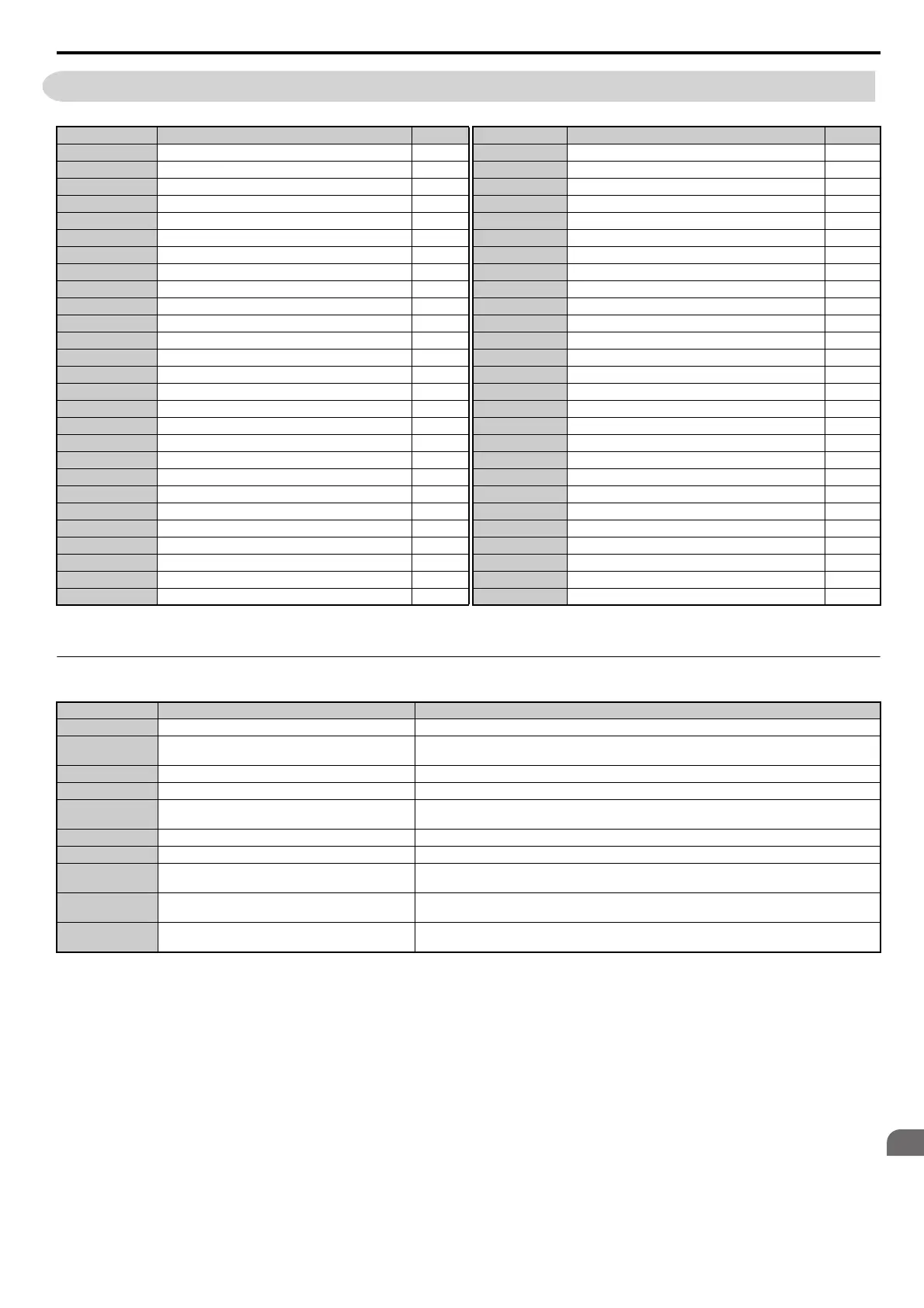
◆ Parameter Differences for models CIMR-E4A0930 and 4A1200
Parameter Group
<1> Specifications differ for models CIMR-E4A0930 and 4A1200. Refer to Parameter Differences for models CIMR-E
4A0930 and 4A1200
on page 359 for details.
Name Page Parameter Group Name Page
A1 Initialization Parameters 360 H6 Pulse Train Input/Output 381
A2 User Parameters 360 L1 <1> Motor Protection 382
b1 Operation Mode Selection 361 L2 Momentary Power Loss Ride-Thru 382
b2 DC Injection Braking and Short Circuit Braking 362 L3 <1> Stall Prevention 383
b3 <1> Speed Search 362 L4 Speed Detection 384
b4 Timer Function 363 L5 Fault Restart 385
b5 PI Control 363 L6 Torque Detection 385
b8 Energy Saving 365 L8 <1> Drive Protection 385
C1 Acceleration and Deceleration Times 366 n1 Hunting Prevention 387
C2 S-Curve Characteristics 366 n3 High Slip Braking (HSB) and Overexcitation Braking 387
C4 Torque Compensation 366 n8 PM Motor Control Tuning 387
C6 <1> Carrier Frequency 367 o1 Digital Operator Display Selection 388
d1 Frequency Reference 367 o2 Digital Operator Keypad Functions 389
d2 Frequency Upper/Lower Limits 367 o3 Copy Function 389
d3 Jump Frequency 368 o4 Maintenance Monitor Settings 389
d4 Frequency Reference Hold and Up/Down 2 Function 368 q DriveWorksEZ Parameters 390
d6 Field Weakening and Field Forcing 368 r DriveWorksEZ Connection Parameters 390
d7 Offset Frequency 368 T1 Induction Motor Auto-Tuning 390
E1 V/f Pattern for Motor 368 T2 PM Motor Auto-Tuning 391
E2 <1> Motor Parameters 369 U1 <1> Operation Status Monitors 391
E5 PM Motor Settings 370 U2 <1> Fault Trace 393
F6 Communication Option Card 371 U3 Fault History 394
H1 Multi-Function Digital Inputs 373 U4 <1> Maintenance Monitors 394
H2 Multi-Function Digital Outputs 376 U5 PI Monitors 396
H3 <1> Multi-Function Analog Inputs 378 U6 Operation Status Monitors 396
H4 Multi-Function Analog Outputs 380 U8 DriveWorksEZ Monitors 397
H5 MEMOBUS/Modbus Serial Communication 380 –––
Parameter Group Name Difference
b3 Speed Search Depends on the b3-04 setting. Refer to b3: Speed Search on page 362 for details.
C6 Carrier Frequency
Defaults and setting ranges differ for C6-02, C6-03, and C6-04. Refer to C6: Carrier Frequency on
page 367 for details.
E2 Motor Parameters Setting units differ for E2-05. Refer to E2: Motor Parameters on page 369 for details.
H3 Multi-Function Analog Inputs H3- = 17 is available in models CIMR-E4A0930 and 4A1200.
L1 Motor Protection
L1-15, L1-16, L1-19 and L1-20 are available in models CIMR-E4A0930 and 4A1200. Refer to L1:
Motor Protection on page 382 for details.
L3 Stall Prevention Refer to L3: Stall Prevention on page 383 for details.
L8 Drive Protection L8-78 is available in models CIMR-E4A0930 and 4A1200 only.
U1 Operation Status Monitors
• Setting units differ for U1-03. Refer to U1: Operation Status Monitors on page 391 for details.
• U1-29 is available in models CIMR-E4A0930 and 4A1200.
U2 Fault Trace
• Setting units differ for U2-05. Refer to U2: Fault Trace on page 393 for details.
• U2-27 and U2-28 are available in models CIMR-E4A0930 and 4A1200.
U4 Maintenance Monitors
• Setting units differ for U4-13. Refer to U4: Maintenance Monitors on page 394 for details.
• U4-32, U4-37, U4-38, and U4-39 are available in models CIMR-E4A0930 and 4A1200.
SIEP_C710616_35.book 359 ページ 2015年11月30日 月曜日 午後2時2分