B.3 Parameter Table
378 YASKAWA ELECTRIC SIEP C710616 35D YASKAWA AC Drive E1000 Technical Manual
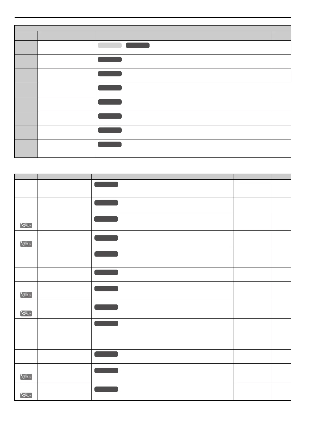
■ H3: Multi-Function Analog Inputs
4B During Short Circuit Braking
Closed: Short Circuit Braking is active.
198
4C During Fast Stop
Closed: A Fast Stop command has been entered from the operator or input terminals.
198
4D oH Pre-alarm Time Limit
Closed: oH pre-alarm time limit has passed.
198
50 Waiting for Run
Closed: Delay excuting any run command until the time set in b1-11 has expired.
198
58 Underload Detection
Closed: Underload is detected.
198
60 Internal Cooling Fan Alarm
Closed: Internal cooling fan alarm
198
90 to 92 DriveWorksEZ Digital Outputs 1 to 3
Reserved for DWEZ digital output functions.
198
100 to 192 Function 0 to 92 with Inverse Output
Inverts the output switching of the multi-function output functions.
Set the last two digits of 1 to reverse the output signal of that specific function.
198
No.(Addr.) Name Description Setting Page
H3-01
(410H)
Terminal A1 Signal Level
Selection
0: 0 to 10 Vdc
1: –10 to 10 Vdc
Default: 0
Min: 0
Max: 1
199
H3-02
(434H)
Terminal A1 Function Selection
Sets the function of terminal A1.
Default: 0
Min: 0
Max: 32
199
H3-03
(411H)
Terminal A1 Gain Setting
Sets the level of the input value selected in H3-02 when 10 V is input at terminal A1.
Default: 100.0%
Min: -999.9%
Max: 999.9%
199
H3-04
(412H)
Terminal A1 Bias Setting
Sets the level of the input value selected in H3-02 when 0 V is input at terminal A1.
Default: 0.0%
Min: -999.9%
Max: 999.9%
199
H3-05
(413H)
Terminal A3 Signal Level
Selection
0: 0 to 10 Vdc
1: –10 to 10 Vdc
Default: 0
Min: 0
Max: 1
200
H3-06
(414H)
Terminal A3 Function Selection
Sets the function of terminal A3.
Default: 2
Min: 0
Max: 31
200
H3-07
(415H)
Terminal A3 Gain Setting
Sets the level of the input value selected in H3-06 when 10 V is input at terminal A3.
Default: 100.0%
Min: -999.9%
Max: 999.9%
201
H3-08
(416H)
Terminal A3 Bias Setting
Sets the level of the input value selected in H3-06 when 0 V is input at terminal A3.
Default: 0.0%
Min: -999.9%
Max: 999.9%
201
H3-09
(417H)
Terminal A2 Signal Level
Selection
0: 0 to 10 Vdc
1: –10 to 10 Vdc
2: 4 to 20 mA Current Input
3: 0 to 20 mA Current Input
Note: Use DIP switch S1 to set input terminal A2 for a current or a voltage input signal.
Default: 2
Min: 0
Max: 3
201
H3-10
(418H)
Terminal A2 Function Selection
Sets the function of terminal A2.
Default: 0
Min: 0
Max: 31
201
H3-11
(419H)
Terminal A2 Gain Setting
Sets the level of the input value selected in H3-10 when 10 V (20 mA) is input at terminal A2.
Default: 100.0%
Min: -999.9%
Max: 999.9%
201
H3-12
(41
AH)
Terminal A2 Bias
Setting
Sets the level of the input value selected in H3-10 when 0 V (0 or 4 mA) is input at terminal A2.
Default: 0.0%
Min: -999.9%
Max: 999.9%
201
H2 Multi-Function Digital Output Settings
H2-
Setting
Function Description Page
OLV/PMV/f
All Modes
All Modes
All Modes
All Modes
All Modes
All Modes
All Modes
All Modes
All Modes
All Modes
All Modes
All Modes
All Modes
All Modes
All Modes
All Modes
All Modes
All Modes
SIEP_C710616_35.book 378 ページ 2015年11月30日 月曜日 午後2時2分