3.11 Terminal A2 Analog Input Signal Selection
YASKAWA ELECTRIC SIEP C710616 35D YASKAWA AC Drive E1000 Technical Manual 89
3.11 Terminal A2 Analog Input Signal Selection
◆ Terminal A2 Input Signal Selection
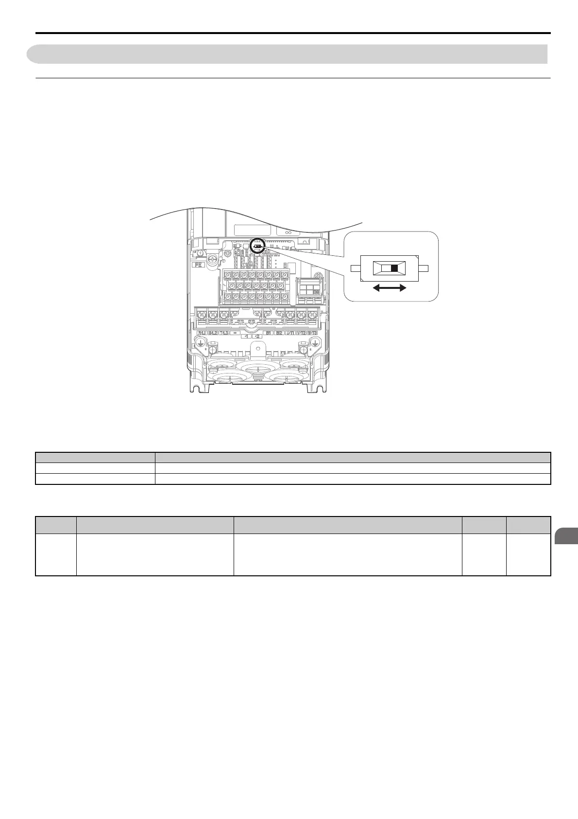
Terminal A2 can be used to input either a voltage or a current signal.
When using input A2 as a voltage input, set DIP switch S1 to “V” (left position) and set parameter H3-09 to 0 (0 to 10
Vdc) or to 1 (-10 to 10 Vdc).
To use current input at terminal A2, set the DIP switch S1 to “I” (default setting) and H3-09 = 2 or 3 (4 to 20 mA or 0 to
20 mA).
To set the DIP switch on the terminal board, use an appropriate sized tool with a tip of approximately 0.8 mm in width.
Figure 3.39
Figure 3.33 DIP Switch S1
Note: If terminals A1 and A2 are both set for frequency bias (H3-02 = 0 and H3-10 = 0), both input values will be combined to create
the frequency reference.
Table 3.18 DIP Switch S1 Settings
Table 3.19 Parameter H3-09 Details
Setting Description
V (left position) Voltage input (-10 to +10 V)
I (right position) (default) Current input (4 to 20 mA or 0 to 20 mA): default setting
No. Parameter Name Description
Setting
Range
Default
Setting
H3-09 Terminal A2 signal level selection
Selects the signal level for terminal A2.
0: 0 to 10 Vdc
1: -10 to 10 Vdc
2: 4 to 20 mA
3: 0 to 20 mA
0 to 3 2
SIEP_C710616_35.book 89 ページ 2015年11月30日 月曜日 午後2時2分