8.5 Installing Peripheral Devices
340 YASKAWA ELECTRIC SIEP C710616 35D YASKAWA AC Drive E1000 Technical Manual
8.5 Installing Peripheral Devices
This section describes the proper steps and precautions to take when installing or connecting various peripheral devices
to the drive.
NOTICE: Use a class 2 power supply (UL standard) when connecting to the control terminals. Improper application of peripheral
devices could result in drive performance degradation due to improper power supply.
◆ Dynamic Braking Options
Dynamic braking (DB) helps bring the motor to a smooth and rapid stop when working with high inertia loads. As the
drive lowers the frequency of a motor moving a high inertia load, regeneration occurs. This can cause an overvoltage
situation when the regenerative energy flows back into the DC bus capacitors. A braking resistor prevents these
overvoltage faults.
NOTICE: Do not allow unqualified personnel to use the product. Failure to comply could result in damage to the drive or braking
circuit. Carefully review the braking resistor instruction manual when connecting a braking resistor option to the drive.
Note: The braking circuit must be sized properly in order to dissipate the power required to decelerate the load in the desired time.
Ensure that the braking circuit can dissipate the energy for the set deceleration time prior to running the drive.
NOTICE: Connect braking resistors to the drive as shown in the I/O wiring examples. Improperly wiring braking circuits could result in
damage to the drive or equipment.
■ Installing a Braking Unit: CDBR Type
To install a CDBR type braking unit, connect the drive’s +3 terminal (CIMR-E2A0169 to 2A0415 and CIMR-
E4A0088 to 4A1200) to the positive terminal on the braking unit. Next wire the negative terminals on the drive and
braking unit together.
Connect the braking resistor to the CDBRs terminals +0 and -0.
Wire the thermal overload relay contact of the CDBR and the braking resistor in series, and connect this signal to a drive
digital input. Use this input to trigger a fault in the drive in case a CDBR or braking resistor overload occurs.
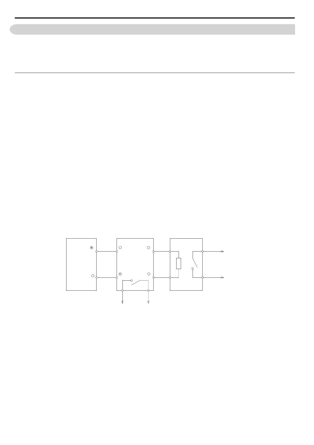
Figure 8.9
Figure 8.9 Connecting a Braking Unit (CDBR type) and Braking Resistor Unit (LKEB type)
(CIMR-E2A0169 to 2A0415, E4A0088 to 4A1200)
Thermal Relay
Trip Contact
Drive
Braking Unit
(CDBR type)
Braking Resistor Unit
(LKEB type)
Thermal Overload
Protector Trip Contact
1
2
P
34
3 + + 0
−− 0
B
+
−
SIEP_C710616_35.book 340 ページ 2015年11月30日 月曜日 午後2時2分