3.9 Control Circuit Wiring
82 YASKAWA ELECTRIC SIEP C710616 35D YASKAWA AC Drive E1000 Technical Manual
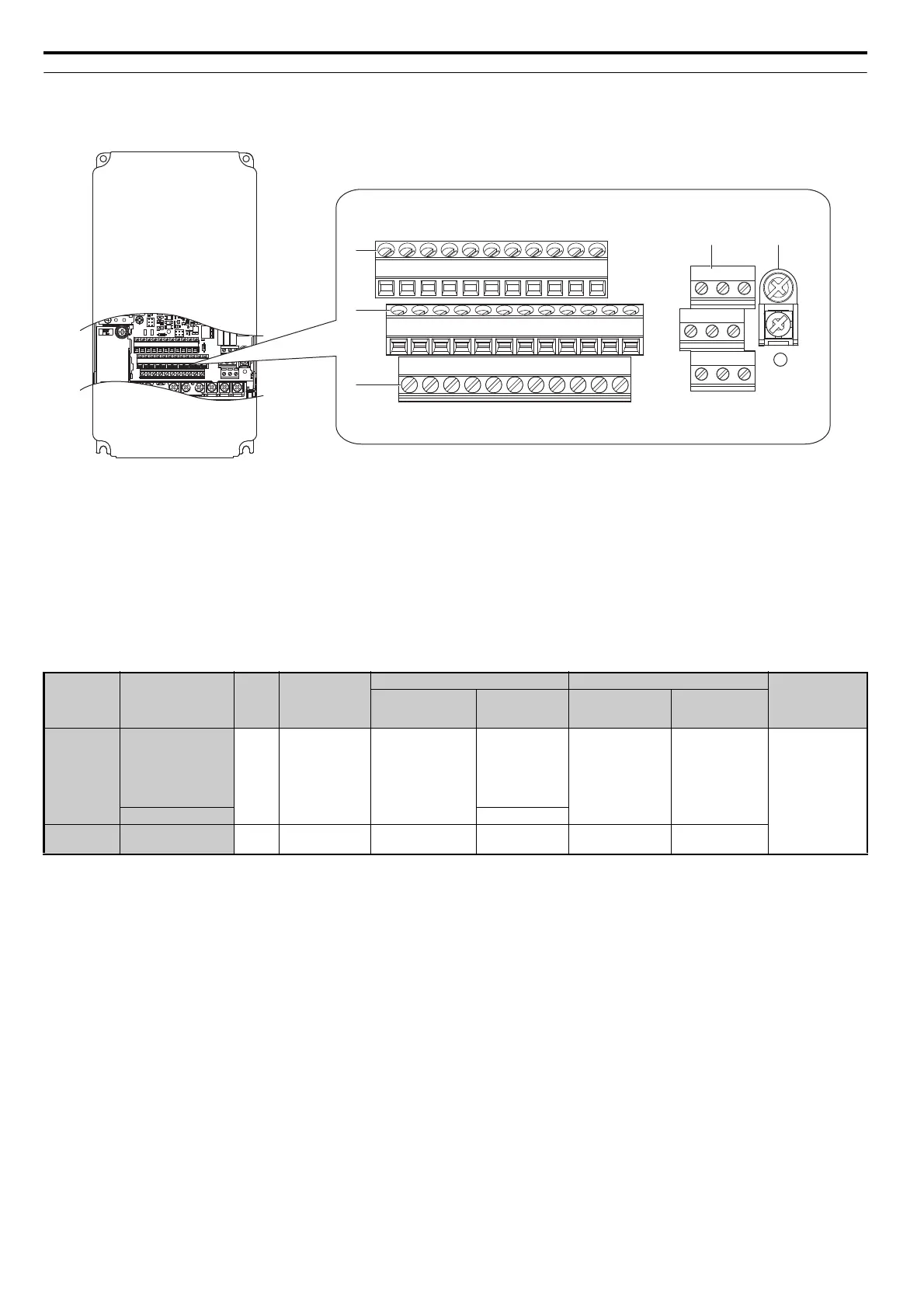
◆ Terminal Configuration
Control circuit terminals should be arranged as shown in Figure 3.24.
Figure 3.31
Figure 3.24 Control Circuit Terminal Arrangement
■ Wire Size and Torque Specifications
Select appropriate wire type and gauges from Table 3.9. For simpler and more reliable wiring, use crimp ferrules on the
wire ends. Refer to Table 3.10 for ferrule terminal types and sizes.
Table 3.9 Wire Gauges and Torque Specifications
A – Terminal Block (TB 2) D – Terminal Block (TB 3)
B – Terminal Block (TB 5) E – Terminal Block (TB 4)
C – Terminal Block (TB 1)
Terminal
Block
Terminal
Screw
Size
Tightening
Torque
Nm
(lb.in.)
Bare Wire Terminal Ferrule-Type Terminal
Wire Type
Applicable
wire size
mm
2
(AWG)
Recommended
wire size
mm
2
(AWG)
Applicable
wire size
mm
2
(AWG)
Recommended
wire size
mm
2
(AWG)
TB1, TB2
TB3, TB4
S1-S8, SC, SP, SN, RP,
+V, -V, A1, A2, A3, AC,
M1-M6, MA, MB, MC,
MP, AM, FM, AC, S+,
S-, R+, R-, IG, HC, H1,
H2, DM+, DM-
M3
0.5 to 0.6
(4.4 to 5.3)
Stranded wire:
0.2 to 1.0 (24 to 17)
Solid wire:
0.2 to 1.5 (24 to 16)
0.75
(18)
0.25 to 0.5
(24 to 20)
0.5
(20)
Shielded line, etc.
E (G) 1.0 (16)
TB5 E (G) M3.5
0.5 to 1.0
(4.4 to 8.9)
0.5 to 2
(20 to 14)
1.25
(12)
––
E
D
C
E(G)
HC H1 H2 DM+ DM- IG R+ R- S+ S-
S1 S2 S3 S4 S5 S6 S7 S8 SN SC SP
V+ AC V- A1 A2 A3 FM AM AC MP RP AC
MA MB MC
M1 M2 M5
M3 M4 M6
BA
SIEP_C710616_35.book 82 ページ 2015年11月30日 月曜日 午後2時2分