2.2 Mechanical Installation
YASKAWA ELECTRIC SIEP C710616 35D YASKAWA AC Drive E1000 Technical Manual 49
Figure 2.10
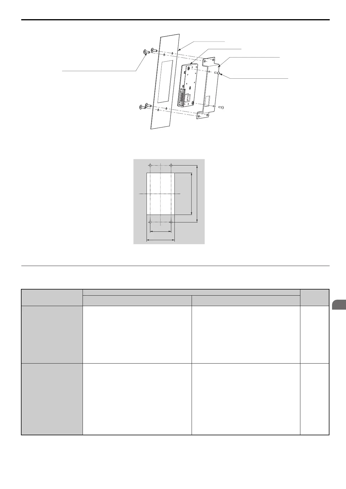
Figure 2.11 Internal/Flush Mount Installation
Note: For environments with a significant amount of dust or other airborne debris, use a gasket between the enclosure panel and the
digital operator.
Figure 2.11
Figure 2.12 Panel Cut-Out Dimensions (Internal/Flush-Mount Installation)
◆ Exterior and Mounting Dimensions
Table 2.3 Drive Models and Types
Protective Design
Drive Model CIMR-E
Page
Three-Phase
200 V Class
Three-Phase
400 V Class
IP20/NEMA 1, UL Type 1
Enclosure
2A0004F
2A0006F
2A0008F
2A0010F
2A0012F
2A0018F
2A0021F
2A0030F
2A0040F
2A0056F
2A0069F
2A0081F
4A0002F
4A0004F
4A0005F
4A0007F
4A0009F
4A0011F
4A0018F
4A0023F
4A0031F
4A0038F
4A0044F
50
IP00 Enclosure
2A0110A
2A0138A
2A0169A
2A0211A
2A0250A
2A0312A
2A0360A
2A0415A
4A0058A
4A0072A
4A0088A
4A0103A
4A0139A
4A0165A
4A0208A
4A0250A
4A0296A
4A0362A
4A0414A
4A0515A
4A0675A
4A0930A
4A1200A
52
Enclosure panel
Unit: mm
Digital Operator
Installation Support Set A
M4 × 10
Phillips truss head screw × 4
(for panel widths between 1 and 1.6)
M3 × 6
Phillips recessed
pan head machine screw × 2
120
45
59
+0.5
0
89
+0.5
0
Unit : mm
SIEP_C710616_35.book 49 ページ 2015年11月30日 月曜日 午後2時2分