8.3 Connecting Peripheral Devices
Peripheral Devices &
Options
8
YASKAWA ELECTRIC SIEP C710616 35D YASKAWA AC Drive E1000 Technical Manual 335
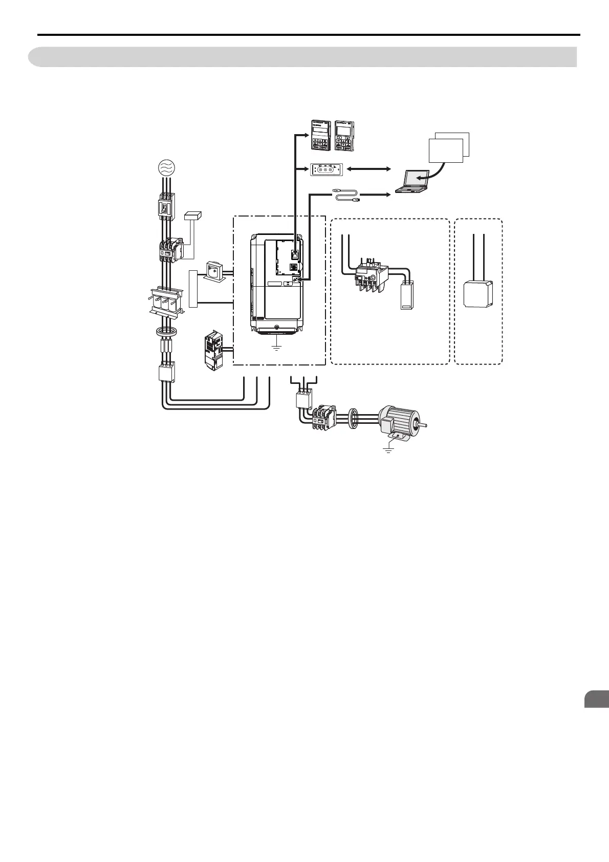
8.3 Connecting Peripheral Devices
Figure 8.1 illustrates how to configure the drive and motor to operate with various peripheral devices.
• For more detailed instructions on how to install each device shown below, refer to the specific manual for that device.
Figure 8.1
Figure 8.1 Connecting Peripheral Devices
Note: Note that if the drive is set to trigger a fault output whenever the fault restart function is activated (L5-02 = 1), then a sequence to
interrupt power when a fault occurs will result in shutting off the power to the drive as the drive attempts to restart itself. The
default setting for L5-02 is 0 (fault output active during restart attempt).
Copy
Verify
Read
LOCK
YASKAWA
JVOP-181
USB Copy Unit
COM ERR
PC
DriveWizard
Engineering Software Tools
DriveWorksEZ
Power
Supply
Line
Breaker
(MCCB)
or
Leakage
Breaker
Magnetic
Contactor
(MC)
Surge
Absorber
DC Reactor
AC Reactor
Zero-phase
Reactor
Fuse
Input Side
Noise Filter
Magnetic
Contactor
(switches to
line power)
Zero-phase
Reactor
Thermal Relay
Braking Resistor Unit
Output Side
Noise Filter
Drive
Ground
B1 B2
Motor
U/T1V/T2W/T3R/L1 S/L2
+2
+1
T/L3
Ground
Momentary
Power Loss
Recovery Unit
USB Copy unit
USB Cable
(Type-AB, sold separately)
LED Operator/LCD Operator
USB Cable
(Type-AB)
Braking Unit
−
+3
24 V control
power supply
unit
SIEP_C710616_35.book 335 ページ 2015年11月30日 月曜日 午後2時2分