8.4 Option Card Installation
336 YASKAWA ELECTRIC SIEP C710616 35D YASKAWA AC Drive E1000 Technical Manual
8.4 Option Card Installation
This section provides instructions on installing the option cards listed in Table 8.1.
◆ Prior to Installing the Option
Prior to installing the option, wire the drive, make the necessary connections to the drive terminals, and verify that the
drive functions normally.
Table 8.2 lists the number of option cards that can be connected to the drive and the drive connector for connecting those
option cards.
Table 8.2 Option Card Installation
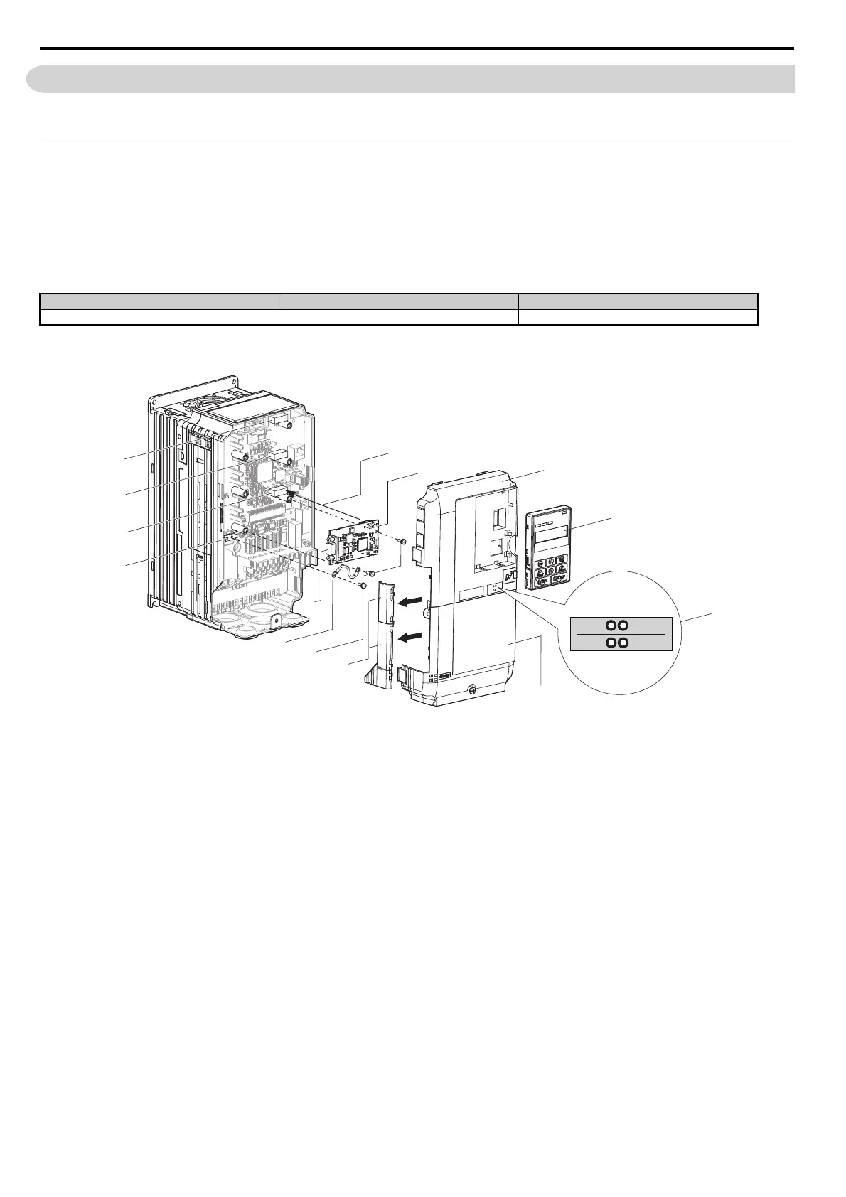
Figure 8.2 shows an exploded view of the drive with the option and related components for reference.
Figure 8.2
Figure 8.2 Drive Components with Option
Option Card Connector Number of Cards Possible
SI-C3, SI-N3, SI-P3, SI-S3, SI-T3 CN5-A 1
A – Insertion point for CN5
<1> LED label varies depending on the option models.
H – Included screws
B – Option card I – Ground wire
C – Front cover J – CN5 communication connector
D – Digital operator K – Drive grounding terminal (FE)
E–LED label
<1> L – Connector CN5-A
F – Terminal cover M – Connector CN5-B
G – Removable tabs for wire routing N – Connector CN5-C
F
H
A
K
L
M
N
I
B
C
D
E
G
J
ERR RUN
BF COMM
SIEP_C710616_35.book 336 ページ 2015年11月30日 月曜日 午後2時2分