8.2 Drive Options and Peripheral Devices
Peripheral Devices &
Options
8
YASKAWA ELECTRIC SIEP C710616 35D YASKAWA AC Drive E1000 Technical Manual 333
8.2 Drive Options and Peripheral Devices
The following table of peripheral devices lists the names of the various accessories and options available for Yaskawa
drives. Contact Yaskawa or your Yaskawa agent to order these peripheral devices.
• Peripheral Device Selection: Refer to the Yaskawa catalog for selection and part numbers.
• Peripheral Device Installation: Refer to the corresponding option manual for installation instructions.
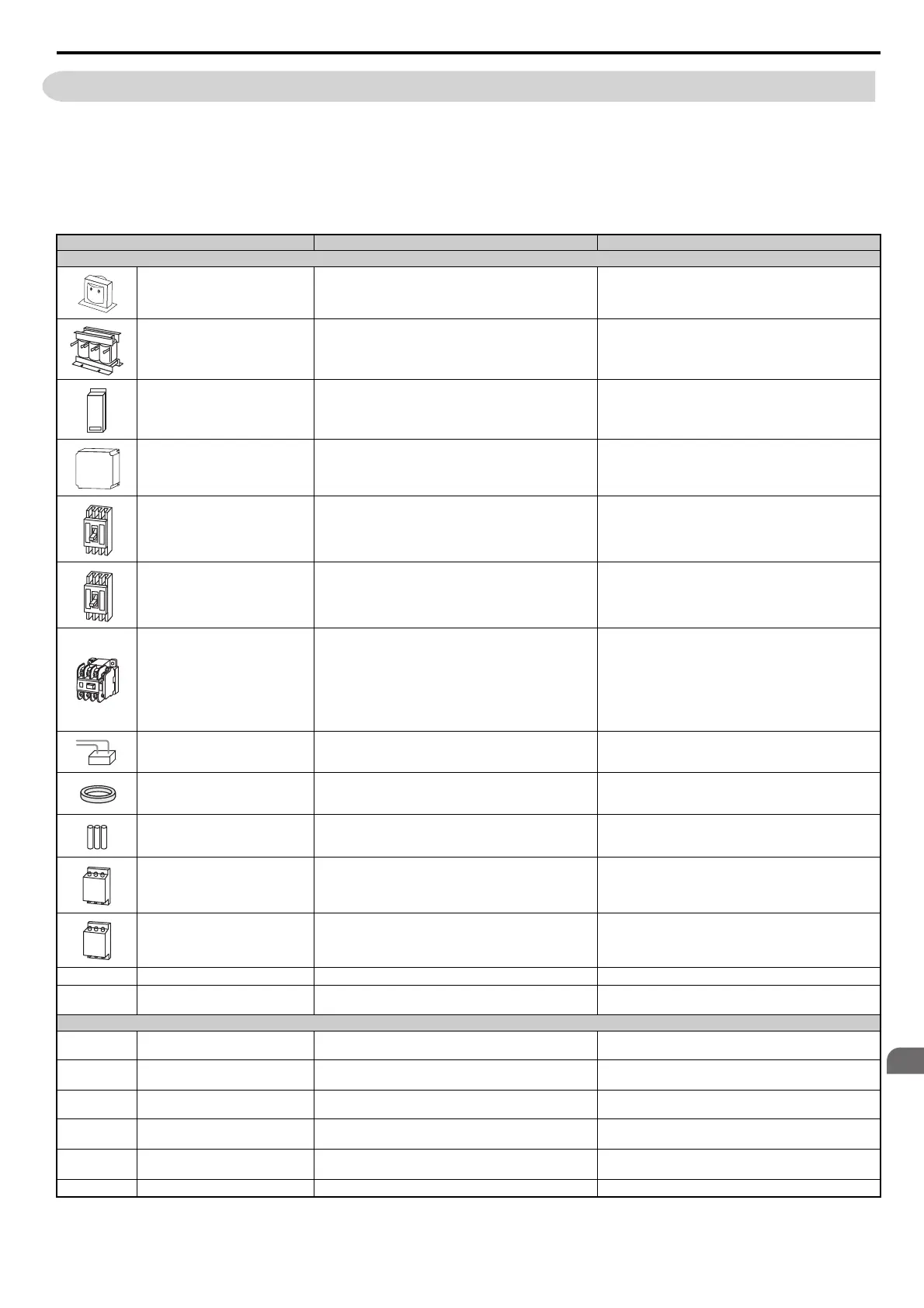
Table 8.1 Available Peripheral Devices
Option Model Number Description
Power Options
DC Reactor
UZDA Series
Improves the power factor by suppressing harmonic distortion
from the power supply.
AC Reactor
UZBA Series
Protects the drive when operating from a large power supply
and improves the power factor by suppressing harmonic
distortion. Highly recommended for power supplies that exceed
600 kVA.
Braking Resistor Unit
LKEB Series
For use with systems requiring dynamic braking with up to
10% ED.
Braking Unit
CDBR Series External braking transistor
Molded Case Circuit Breaker
NF Series
Circuit breaker for short circuit or over load protection
Note: Yaskawa recommends installing an MCCB to the power
supply side to protect drive wiring and prevent other damage in
the event of component failure. Install an MCCB if permitted
by the power system.
Earth Leakage Circuit Breaker
(ELCB)
NV, EG, or SG Series
Provides protection against potentially harmful leakage current.
Note: Yaskawa recommends installing a LECB to the power
supply side to protect drive wiring and prevent other damage in
the event of component failure. An MCCB can also be used if
permitted by the power system.
Magnetic Contactor (Input)
SC Series
Ensures that power to drive is completely shut off when
necessary, preventing potential damage to the braking resistor
and other internal circuitry.
Install an MCCB when using a braking resistor to prevent the
braking resistor from overheating.
To protect internal components from sudden high levels of
input current, the MC should be wired so that it opens when a
fault output terminal is triggered.
Surge Protector
200 V class: DCR2-A
400 V class: RFN3AL-504KD
Suppresses surge voltage caused by magnetic contactor
switching.
Zero Phase Reactor
F6045GB, F11080GB Reduces electromagnetic noise.
Fuse
200 V class: CR2LS or CR2L Series, FWX Series
400 V class: CR6L Series, FWH Series
Protects the drive in case of short circuit.
Input Noise Filter
LNFB, LNFD, FN Series
Reduces electromagnetic noise flowing back from the drive
into power supply.
Output Noise Filter
LF-310 Series Reduces electromagnetic noise generated by the drive output.
—
Isolator
DGP Isolates the drive control I/Os for improved noise resistance.
—
Momentary Power Loss Recovery
Unit
200 V class: P0010
400 V class: P0020
Ensures drive operation during momentary power loss up to 2 s
Reference Setting / Monitor Options
—
Frequency Meter / Ammeter
DCF-6A
External meter for displaying the output frequency or current
using an analog signal from the drive
—
Frequency Meter Potentiometer (20
kΩ)
RH000850
External potentiometer for adjusting the frequency meter
scaling
—
Output Voltage Meter
SDF-12NH
External meter for displaying the output voltage using an
analog signal from the drive
—
Frequency Setting Potentiometer (2
kΩ)
RH000739
External potentiometer for setting the frequency reference by
an analog input
—
Control Dial for Frequency Setting
Potentiometer
CM-3S Control dial for frequency setting potentiometer
—
Meter Plate
NPJT41561-1 Plate with scale for frequency setting potentiometer
SIEP_C710616_35.book 333 ページ 2015年11月30日 月曜日 午後2時2分