3.8 Main Circuit Wiring
72 YASKAWA ELECTRIC SIEP C710616 35D YASKAWA AC Drive E1000 Technical Manual
3.8 Main Circuit Wiring
This section describes the functions, specifications, and procedures required to safely and properly wire the main circuit
in the drive.
NOTICE: Do not solder the ends of wire connections to the drive. Soldered wiring connections can loosen over time. Improper wiring
practices could result in drive malfunction due to loose terminal connections.
NOTICE: Do not switch the drive input to start or stop the motor. Frequently switching the drive on and off shortens the lifetime of the
DC bus charge circuit and the DC bus capacitors, and can cause premature drive failures. For the full performance life, refrain from
switching the drive on and off more than once every 30 minutes.
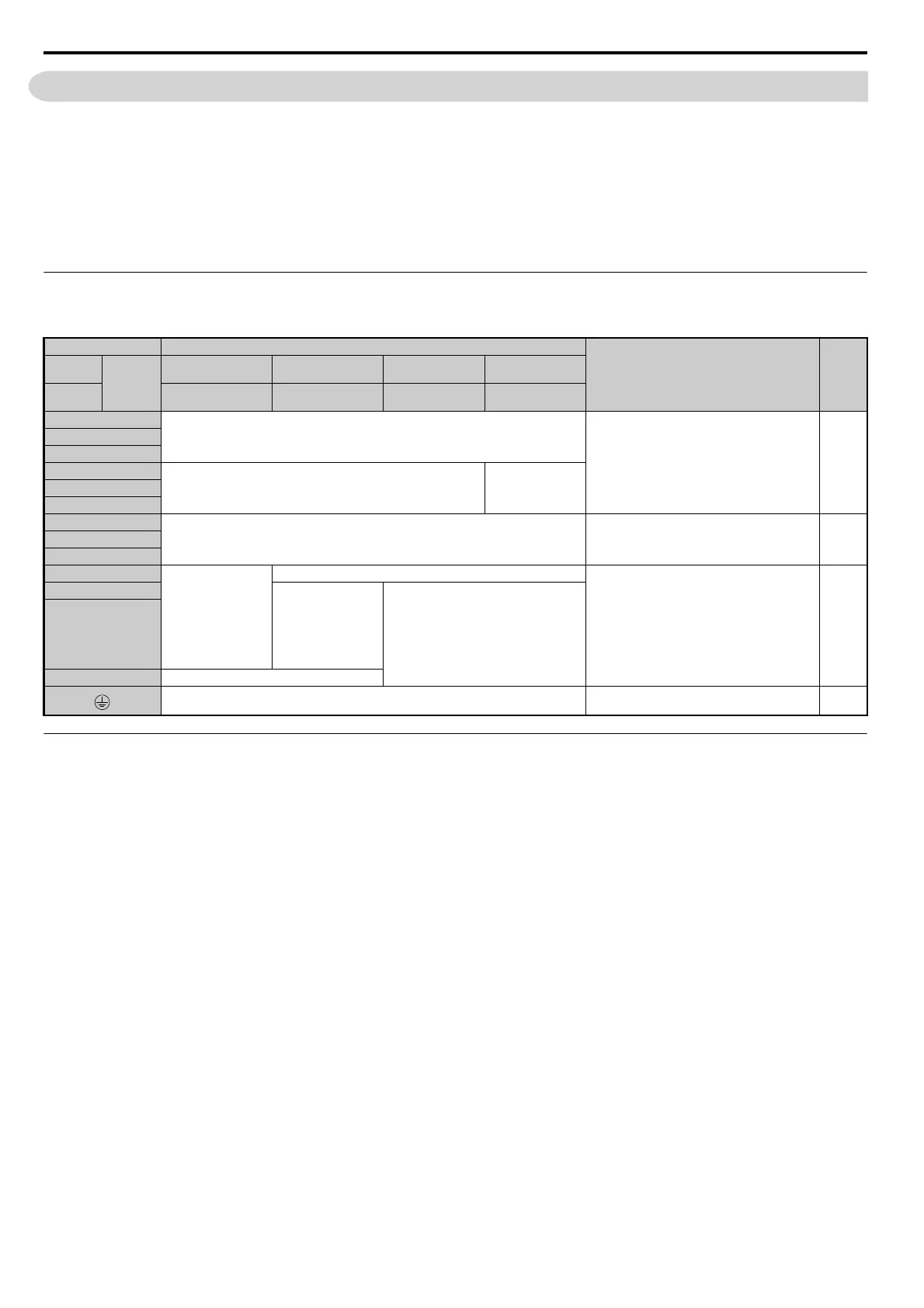
◆ Main Circuit Terminal Functions
Table 3.2 Main Circuit Terminal Functions
◆ Protecting Main Circuit Terminals
■ Insulation Cap
Use insulation caps when wiring the drive with crimp terminals. Take particular care to ensure that wiring does not touch
neighboring terminals or the surrounding case.
■
Insulation Barrier
Insulation barriers are packaged with drive model CIMR-E4A0414 through 4A1200 to provide added protection
between terminals. Yaskawa recommends using the insulation barriers provided to ensure proper wiring. See Figure 3.19
for instructions on where the insulation barriers should be placed.
Terminal Type
Function Page
200 V
Class
Model
CIMR-E
2A0004 to 2A0081 2A0110, 2A0138 2A0169 to 2A0415 –
400 V
Class
4A0002 to 4A0044 4A0058 to 4A0072 4A0088 to 4A0675 4A0930, 4A1200
R/L1
Main circuit power supply input
Connects line power to the drive 59
S/L2
T/L3
R1-L11
not available
Main circuit power
supply input
S1-L21
T1-L31
U/T1
Drive output Connects to the motor 59
V/T2
W/T3
+2 • DC reactor
connection (+1, +2)
(remove the shorting
bar between +1 and
+2)
• DC power supply
input
(+1, –)
not available
For connection
• of the drive to a DC power supply (terminals +1
and – are not EU or UL approved)
• of dynamic braking options
• of a DC reactor
343
+1
• DC power supply
input
(+1, –)
• DC power supply input (+1, –)
• Braking unit connection (+3, –)
–
+3 not available
For 200 V class: 100 Ω or less
For 400 V class: 10 Ω or less
Grounding terminal 78
SIEP_C710616_35.book 72 ページ 2015年11月30日 月曜日 午後2時2分